Interference - mutual strengthening or weakening of two or more waves when they overlap each other.
As a result interference there is a redistribution of the energy of light radiation in space. A stable (stationary, time-constant) interference pattern is observed when adding coherent waves.
Latin word "cohaerens" means "connected." And in full accordance with this meaning, coherence is understood as the correlated occurrence in time and space of several wave processes.
Requirement wave coherence- key when considering interference. Let's analyze it using the example of adding two waves of the same frequency. Let them excite equally directed ( E̅ 1 E̅ 2) fluctuations: E̅ 1 sin (ω̅ t+φ 1 -) And E̅ 2 sin (ω̅ t+φ 2 -). Then the amplitude of the resulting oscillation E̅ sin (ω̅ t+φ) equal to
E = √(E 1 2 +E 2 2 + 2 E 1E 2 cos δ),
Where δ = φ 1 —φ 2. If the phase difference δ constant in time, then the waves are called coherent.
For not coherent waves δ varies randomly over time, so the average value of cos δ equals zero. Since the intensity of the wave is proportional to the square of the amplitude, then in the case addition of incoherent waves resultant wave intensity I is simply equal to the sum of the intensities of each wave:
I =I 1 + I 2.
At addition same coherent waves intensity of the resulting vibration
I =I 1 + I 2 + 2√(I 1I 2 cos δ ),
depending on cos value δ , can take values both greater and less than I 1 +I 2. Since the value δ in the general case depends on the observation point, then the intensity of the resulting wave will be different at different points. This is precisely what was meant when we spoke above about the redistribution of energy in space during the interference of waves.
Radiation with a high degree of coherence is obtained using lasers. But if there is no laser, coherent waves can be obtained by dividing one wave into several. Typically, two methods of “division” are used: wavefront division and amplitude division. When dividing the wave front, wave beams interfere, initially propagating from one source in different directions, which are then brought together using optical instruments in one region of space (called interference field). For this they use bezels And Fresnel bi-prisms, Biye lenses and etc.
To list the “colors” of different parts of the optical range in descending order of wavelength - red, orange, yellow, green, blue, indigo, violet, just remember the phrase: “Every hunter wants to know where the pheasant sits "
With amplitude division, the wave is divided at the semitransparent boundary of two media. Then, as a result of subsequent reflections and refractions, the separated parts of the wave meet and interfere. This is how they are painted different colors soap bubbles and thin oil films on water, dragonfly wings and oxide films on metals and window glass. It is important that arcs of waves emitted in one act of radiation from an atom or molecule must interfere, i.e., parts of the wave must move separately “for a short time,” otherwise waves emitted by different atoms will already arrive at the meeting point. And since atoms emit spontaneously (if not created special conditions, as in lasers), then these waves will obviously be incoherent. Lasers use stimulated emission and this achieves high degree coherence. Material from the site
Phenomenon interference Sveta in the 17th century Newton explored. He observed the interference of light in a thin air gap between a glass plate and a lens placed on it. The interference pattern obtained in such an experiment is called - Newton's rings. However, Newton was unable to clearly explain the appearance of rings within the framework of his corpuscular theory of light. Only in early XIX centuries, first T. Jung and then O. Fresnel were able to explain the formation of interference patterns. Both of them were supporters of the wave theory of light.
DEFINITION
The phenomenon of interference called the superposition of oscillations and their mutual strengthening or weakening.
Interference manifests itself as an alternation of intensity maxima and minima. The result of interference is called an interference pattern. The word interference is of French origin and means to interfere.
The phenomenon of wave interference is possible when oscillations occur at equal frequencies, have the same directions of displacement of particles in space, and the phase differences of oscillations are constant, that is, if the sources of oscillations are coherent. (The word cohaerer is translated from Latin as being in connection). Empty, one set of traveling waves creates sequentially at each point of the considered part of the wave field, identical oscillations. In this case, it is superimposed on a set of similar waves that are coherent with the first and have the same amplitude, then the phenomenon of interference leads to a constant stratification of the wave field over time into areas of increased oscillations or areas of their weakening.
The location of the interference amplification of oscillations is determined by the difference in the wave paths (). Maximum amplification of oscillations is achieved if:
K is an integer; - wavelength.
Oscillations are most weakened if:
![]()
Any type of wave can interfere. Historically, interference was first discovered in light waves by R. Boyle and R. Hooke, who observed the appearance of color in thin films. T. Jung introduced the concept of the principle of superposition of waves, explained the essence of the phenomenon and used the term interference. Jung was the first to experiment with the interference of light. He obtained an interference pattern from two slits, which later became a classic experiment. In this experiment light wave from one narrow slit it fell on the screen, which had two more narrow slits. On the demonstration screen, beams of light from the last two slits overlapped each other. In the overlap region, an interference pattern arose from light and dark stripes. The theory created by Jung explained the phenomenon of interference when two monochromatic waves of the same frequencies are superimposed. Jung was the first to realize that interference cannot be obtained when dealing with independent light sources.
Stationary and non-stationary interference
Interference is divided into stationary and non-stationary. A stationary interference pattern occurs only in the case of completely coherent waves.
As a result, energy is redistributed in space. Energy is concentrated in the maximums, but does not reach the minimums at all. The redistribution of wave energy in space during interference corresponds to the law of conservation of energy. The energy of the wave resulting from interference will be equal to the sum of the energies of the creeping waves (on average).
When incoherent waves are superimposed, no interference phenomenon is observed.
The condition for interference maxima for a wave of light is the expression:
Wavelength of light in a vacuum; — optical difference in the path of the rays. Optical path difference () is the difference in optical lengths that waves travel:
L is the optical path length ( geometric length path (s), multiplied by the refractive index of the medium (n)):
If the equality holds:
![]()
then a minimum is observed at the point in question. Expression (6) is called the interference minimum condition.
Examples of problem solving
EXAMPLE 1
| Exercise | The wavelengths of visible light range from 380 nm to 760 nm. Which waves from this range will be maximally amplified with an optical path difference |
| Solution | The condition for maximum light intensity during interference is: Let us express the wavelength of light from condition (1.1):
Let's consider different values of k.
Let's see which of the obtained wavelengths fall within the visible wavelength range of 380 (nm |
| Answer |
EXAMPLE 2
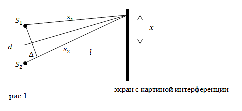
| Exercise | What is the distance from the coherent light sources to the demonstration screen in Young's experiment (l), the distance between these sources is d, the length of the light is , the distance between the fringes in the middle of the interference pattern is b? Accept that. |
| Solution | Let's make a drawing. From Fig. 1, according to the Pythagorean Theorem, we have: |
Physics textbooks give the following definition of interference.
Interference is the phenomenon of interaction in space of several (two or more) coherent waves, in which there is an amplification or weakening of the resulting wave, depending on what phase the wave is in at a given point in space.
Only coherent waves can interfere. Maximums are observed at a stroke difference equal to length waves. It is obvious that the effects of bions coming from different slits mutually reinforce each other. Minima are observed when the path difference is equal to an odd number of half-waves and the oscillations from different slits cancel each other out.
Light interference is the spatial redistribution of light flux during the interaction of two (or several) coherent waves, as a result of which minima and maxima of its intensity appear in different places.
Sight general theory Interference interactions can be easily shown using animation.
At the top and bottom the path difference is equal to half the wavelength. Bions transmitting electromagnetic waves from different slits rotate in antiphase. As a result, we have a minimum of illumination.
In the figure in the center, the path difference is equal to the whole wavelength (or zero), and the oscillations (rotations of bions) from different slits coincide, which gives the maximum illumination (the strongest darkening of the photographic plate).
Looking at the interference picture shown in the animation, you should understand that the bion rotations shown would take place if one of the slits were closed. In the case when both slits are open, the total rotation in the bright areas will be equal to zero (that is, the light does not seem to get into this place, and the photographic plate is not exposed). In dark areas, the influence of rays from different slits will add up and have a double effect.
If you have any questions, check out the page Electromagnetic waves, definitions and description.
.
The method of rotating amplitude vector, given in textbooks, in this case describes everything very clearly.
From an arbitrary point O, selected on the X-axis, at an angle equal to the initial phase of the oscillations, vector A is plotted, the modulus of which is equal to the amplitude of the oscillation in question. If this vector is brought into rotation with angular velocity, then the projection of the vector will move along the X axis in the range from – A to + A, and the oscillating value will change over time according to the law. Consequently, the projection of the end of the amplitude vector onto the axis will perform harmonic oscillations with amplitude A, with a circular frequency equal to angular velocity rotation of the vector, and with the initial phase, equal to the angle, which forms vector A with the X axis at the initial time. Nothing will change if you apply this method when adding rotations of vectors for three-dimensional space.
Interference is the result of the addition of bion rotations from various (slots) sources of electromagnetic oscillations.
So we gave mathematical basis for the principle of field superposition, both electromagnetic and gravitational.In fact, incoherent waves also interfere, but the speed of the human eye does not have time to notice differences in illumination, since it (illuminance) changes very quickly for each point. The interference pattern turns out to be “floating.” Now, knowing that several types of rotation can overlap each other, the picture becomes clear when polarization of light .
The electric field created by nuclei and electrons in atoms and obstacles in the form of the atoms themselves naturally slow down the process of propagation of vibrations, hence the decrease in the speed of light in optically dense media.
Let us ask the question, where do the wave properties of particles come from? And we can answer it easily. They (wave properties) are a consequence of changes in the location of bions due to the movement of a particle through these bions. That is, when a particle moves, bions change their location, and such a change in location will take the form of an electromagnetic wave.
Now we will show that Planck's formula does not imply quantization of energy at all. This formula includes a variable such as frequency, which is continuous. And the discreteness appears because we simply do not have instruments capable of recording less than a full revolution of the bion. So we passed the Heisenberg uncertainty principle. The conclusions from which clearly contradict the principle of continuity. Let's figure it out.
One of the formulas expressing this principle looks like this. Let's look at this equation carefully. Let us first assume that the particle is moving at a very low speed. What prevents us from determining its position? Analyzing existing methods, for example, illuminating it with a photon, we come to the conclusion that such an action will lead to a significant change in momentum. But this only means that we simply do not have a suitable “line”. This issue is discussed in more detail on the page electron diffraction .
Now about the particle speed. Let's look at what speed is. Having not yet reached any regularities, we encounter a limitation in the form of the fact that bodies are considered as material points. But obviously this is not the case. All bodies have a certain extent (and the photon too), which also becomes necessary to establish (and for this, again, we do not have the opportunity).
Conclusion: we do not have tools for such measurements. But this does not mean at all that the particle moves along an indefinite trajectory (without a trajectory).
Analysis of the Schrödinger equation used to calculate the shape of orbitals.
In this regard, let us consider the Schrödinger equation, one of the conclusions of which is the assumption that microparticles have no trajectory. Let us present our objections.
- The Schrödinger equation is a postulate, that is, a statement that is not based on anything.
- The Schrödinger equation on its right side has an imaginary unit i and therefore should not describe real physical parameters (as we remember from mathematics, the geometric representation of imaginary numbers leads to another coordinate plane, but how then are real physical quantities translated into it).
- To solve the Schrödinger equation, several normalization conditions are used, which are chosen arbitrarily, only in order to obtain a result that coincides with experiment.
- The shape of electron orbitals used in chemistry, obtained using the Schrödinger equation, dubiously reflects the distribution of electron densities in an atom. Moreover, it also requires the use of the Pauli exclusion principle, which, by the way, is also not based on anything. On other pages we will show the real physical meaning Pauli principle.
- In the Schrödinger equation for stationary states simplification is made inappropriately when U ( potential energy) does not depend on time.
Electrons move relative to each other and relative to the nucleus.
Therefore, the potential energy changes. This equation also does not take into account the magnetic effects that arise during the movement of electrons.
Let's refute the conclusion
that, obeying the Schrödinger equation in their movement, the particles supposedly lose their trajectory.
Let me remind you that the psi function describes the movement of particles.
Quote. “In accordance with its meaning, the psi function must be unambiguous, continuous and finite (except, perhaps, for special points). Moreover, she must have a continuous and finite derivative . The set of listed requirements is called standard conditions”*(11). I propose to remember that the continuity of a function is a necessary condition for the existence of a derivative. But continuity of function implies continuity of argument change.
Conclusion: the standard conditions imposed on the psi function do not allow the argument, that is, the coordinates X, Y, Z, to change abruptly (or undergo a discontinuity). Consequently, they, the coordinates, change continuously. And this means only one thing. Any particle cannot but have a trajectory.
(But, amazing thing. The Schrödinger equation just had to be interpreted differently, and then everything would fall into place).
In this regard, the entire theory of atomic structure, based on the Schrödinger equation, collapses, the consequence of which is the assumption of the so-called orbitals in which the electron supposedly moves.
It may be objected that when electron diffraction uncertainty arises in the deflection angle. Well, let’s look at electron diffraction separately (explanations on the page electron diffraction).
Understanding that bions fill all space, you can see that when moving through them, any particle will cause a change in their location, that is, it will rotate the bions around their axis in a certain way. I argue that it is precisely this change in the location of bions that scientists call the wave properties of particles. It is not difficult to notice that changes in the location of bions will depend on the mass of the moving particle, its speed and charge. For some reason, charge is not present in de Broglie's formula. Apparently, this is all due to the eternal desire to separate processes. Or the charge is simply equal in this case to +1 or -1. In principle, there really is no difference in which direction (clockwise or counterclockwise) the bions rotate (provided that the charge is equal to +1 or -1).
Summarize. Interference is a phenomenon based on the addition of particle vibrations physical vacuum, can be clearly explained using the rotating amplitude vector method. We have given this explanation of interference on this page.
Interference - history of discovery and research
The principle of interference was discovered in 1802, when the Englishman T. Young, a doctor by profession, a man with very diverse interests, conducted the now classic “two-hole experiment.” Two closely spaced holes were pierced in the screen with the tip of a pin, which were illuminated by sunlight from a small hole in the curtained window. Behind the screen, Jung observed, instead of two bright dots, a series of alternating dark and light rings.
He explained his experience by analogy with the propagation of two different wave systems on the surface of water.
“I believe,” Jung wrote, that similar phenomena occur when two portions of light are mixed, and this superposition I call the general law of interference.”
To observe the phenomenon of interference, coherent sources are needed that emit waves with a fixed phase difference. Such sources can be obtained by splitting a beam of light from a conventional source (for example, using a translucent mirror). The two beams thus formed are then directed onto the screen using optical systems. Since both beams have the same origin, the phase difference at each location of the screen is fixed (it depends only on the difference in length optical paths). An interference pattern appears on the screen.
A typical example of an interference phenomenon that can be observed is the coloration of thin films (gasoline stains on asphalt, soap films). In this case, interference occurs between the rays reflected from the outer and inner surfaces of the film. The thickness of the film usually varies from place to place, and it appears to be painted in all the colors of the rainbow.
It is interesting that Newton studied the problem of interference, and since he was of the opinion that light consists of tiny particles (corpuscles), he had to attribute strange “attacks” of light and heavy reflection to these particles to explain the coloring of thin plates. But Jung easily explained this phenomenon based on interference and even measured the wavelength of light for the first time, and with very good accuracy.
A special type of interference pattern arises when direct and reflected waves are added. In this case, so-called standing waves are formed.
In the simplest case, when a plane wave is reflected from flat wall a system of fixed maxima and minima appears, located parallel to the wall. When reflected at an angle, the picture becomes more complicated.
Another example of wave interference is the so-called Chladni figures. Sand is poured onto a plate fixed at one point, and a bow is drawn along its edge. The sand collects on certain lines, the appearance of which depends on the shape of the plate and the position of the fixed point.
In this case sound waves, excited by the bow, are reflected from its edges (it is no coincidence that the explanation of the echo also belongs to Chladni). At each place on the plate, vibrations with different phase shifts are added together. As a result, nodal points appear - where the oscillations cancel each other out, and antinodes - where they are maximally amplified. Sand is thrown from the antinodes and collected at the nodal lines. The theory of these figures, discovered by the famous German acoustician Chladni in 1787, was created by the French scientists Laplace and Poisson.
The phenomenon of interference is characteristic feature wave processes of any nature.
Interference is the addition of waves in space, in which a time-constant distribution of the amplitudes of the resulting oscillations is formed. During interference, a spatial redistribution of wave energy occurs. At some points there is a concentration of energy (interference maxima), at others - damping of waves (interference minima). The reason for the redistribution of energy is the difference in the phases of oscillations in the folding waves. Prerequisite- wave coherence.
2.Coherent light sources, methods of obtaining them.
Waves of the same frequency are called coherent, the phase difference of which does not change with time at each point of the wave field.
In addition, the field oscillations in these waves must occur in the same plane.
Jung's experience
Thomas Young observed interference from two sources by piercing two small holes in an opaque screen at a short distance (d ≈ 1 mm). The holes were illuminated by light from the sun passing through a small hole in another opaque screen. Elements of fluid mechanics Pressure in liquid and gas Gas molecules, performing random, chaotic movement, are not connected or very weakly connected by interaction forces, therefore they move freely and, as a result of collisions, tend to fly apart in all directions, filling the entire volume provided to them, i.e., the volume of gas is determined by the volume of the container that the gas occupies.
Fresnel mirrors

Light from a narrow slit S falls on two flat mirrors, rotated relative to each other at a very small angle φ. Using the law of light reflection (17.1.3.) it is easy to show that the incident beam of light will split into two, emanating from imaginary sources S1 and S2. The source S is covered from the observation screen with an opaque screen.
Fresnel biprism
Two glass prisms with a small refractive angle θ are made from one piece of glass so that the prisms are folded with their bases. The light source is a brightly illuminated slit S. After refraction in the biprism, the incident beam is split into two, emanating from imaginary sources S1 and S2, which give two coherent cylindrical waves.
Since the refractive angle θ is small, all rays are deflected by each of the halves of the biprism by the same angle φ. It can be shown that in this case n is the refractive index of the prism material.
Newton's rings
A plano-convex lens of large radius is placed on a glass plate and illuminated from above parallel beam Sveta. Since the radius of the lens R is large compared to r - the radius of the interference fringes, the angle of incidence of light on the inner surface of the lens i ≈ 0. Then the geometric path difference with great accuracy is equal to 2b. When finding the optical path difference, one should take into account the change in phase to the opposite one upon reflection from an optically denser medium. The connection between b, r and R is not difficult to find from geometric considerations. 
3. Conditions for maxima and minima during interference. Geometric and optical differences in the path of rays. Optical path length.
The result of the addition of waves arriving at the observation point M from two coherent sources O1 and O2 depends on the phase difference between them Df (see Fig. 1.)  The distances traveled by the waves from the sources to the observation point are equal to d1 and d2, respectively. The quantity is called the geometric path difference Dd = d2- d1. This value determines the phase difference of oscillations at point M. Two limiting cases of wave superposition are possible.
INTERFERENCE OF LIGHT- spatial redistribution of the energy of light radiation when two or more are superimposed. light waves, special case general phenomenon wave interference. Certain phenomena of I. s. were studied by I. Newton in the 17th century, but could not be explained by him from the point of view of his corpuscular theory. Correct explanation of I. s. as a typical wave phenomenon was given in the beginning. 19th century T. Young (Th. Young) and O. Fresnel (A. Fresnel). Naib, I.S. is widely known, characterized by the formation of a stationary (constant in time) interference pattern (I.P.) - a regular alternation in space of areas of higher intensity. and down. light intensity resulting from the superposition of coherent light beams, i.e., under conditions of a constant (or regularly changing) phase difference. Less often and only in special cases. Under experimental conditions, non-stationary laser phenomena are observed, which include light beats and intensity correlation effects. A rigorous explanation of the phenomena of non-stationary I.S. requires taking into account both wave and corpuscular properties light and is given on the basis of quantum. Stationary I. s. occurs when there is coherence(determining phase correlation) of superimposed waves. Mutually beams of light can be obtained by dividing and then combining rays emanating from a common light source. In this case, the coherence requirement imposes certain restrictions on the angle. dimensions of the source and the width of the radiation spectrum.
Education and. it is convenient to trace on the idealized diagram of the classical. Young's experiment (Fig. 1).
Point light source S with wavelength l illuminates two small holes in the screen A, which become secondary mutually coherent light sources (see. Diffraction of light).On the screen IN observed and k., caused interference two created wave systems. In accordance with superposition principle electric-magnetic tension fields E Q at an arbitrary point Q of the screen IN is given by the sum of the field strengths E 1Q and E 2Q created at point Q by sources 1 and 2. The observed quantity is the intensity of radiation incident on the screen, proportional to av. the square of the field strength. Representing the field strength E i (t, s) each source (i=1,2) harmonic. function of time t and distance s along the direction of propagation
E i ( t,s)=E icos2p( vt+s/ l+j 0),
where l is the wavelength, v- frequency, j 0 - start. phase of light, it is possible, with proper choice of units of measurement of field strength, to obtain an expression for the intensity I Q at point Q in the form:
Here I 1 =

Interference fringes are observed in monochromatic. light in any plane of the area of overlap of divergent beams from sources S 1 and S 2 (shown by shading). From interference devices with wavefront division are very practical. is important in spectroscopy. lattice. All schemes of I.s. with wavefront division, they impose strict requirements on the smallness of the angle. size of the light source. For example, in Young’s experiment, when illuminating holes 1 and 2 with direct sunlight, i.e., a source with an angle. size of only 0.5°, to obtain clear and... k. The distance between the holes should not exceed several. tens of microns. It is on the sharp criticality of the contrast and. Since the method of measuring angle is based on the size of the source in circuits with wavefront division. star sizes using a stellar interferometer (see. Stellar interferometer). In the diagrams of I. s. with amplitude wavefield division, the radiation from the primary source is divided by translucent optical interfaces. avg. So, for example, a widespread natural phenomenon arises. conditions of I.s. in thin films, responsible for the iridescent coloring of oil stains on water, soap bubbles, insect wings, oxide films on metals, etc. In all these cases, an IR occurs, reflected by two surfaces of the films. In thin films AC thickness when illuminated by an extended light source, the interference pattern. the bands are perceived to be localized on the surface of the film, and this interference. the strip corresponds to a fixed film thickness ( strips of equal thickness.; rice. 3). Bright interference coloring occurs only for very thin films with a thickness of the order of the wavelength, i.e., in low interference orders. For thicker films etc. K. is visible when illuminated with monochromatic light, for example, in the light of a low-pressure sodium lamp. In thin films strictly