Lorentz force Lorentz force Modulus of Lorentz force. Lorentz force modulus. Direction of the Lorentz force Direction of the Lorentz force Left hand rule Left hand rule Flat trajectories of charged particles in a uniform magnetic field Flat trajectories of charged particles in a uniform magnetic field Questions on the topic. Questions on the topic. Lorentz force Lorentz force Modulus of Lorentz force. Lorentz force modulus. Direction of the Lorentz force Direction of the Lorentz force Left hand rule Left hand rule Flat trajectories of charged particles in a uniform magnetic field Flat trajectories of charged particles in a uniform magnetic field Questions on the topic. Questions on the topic.


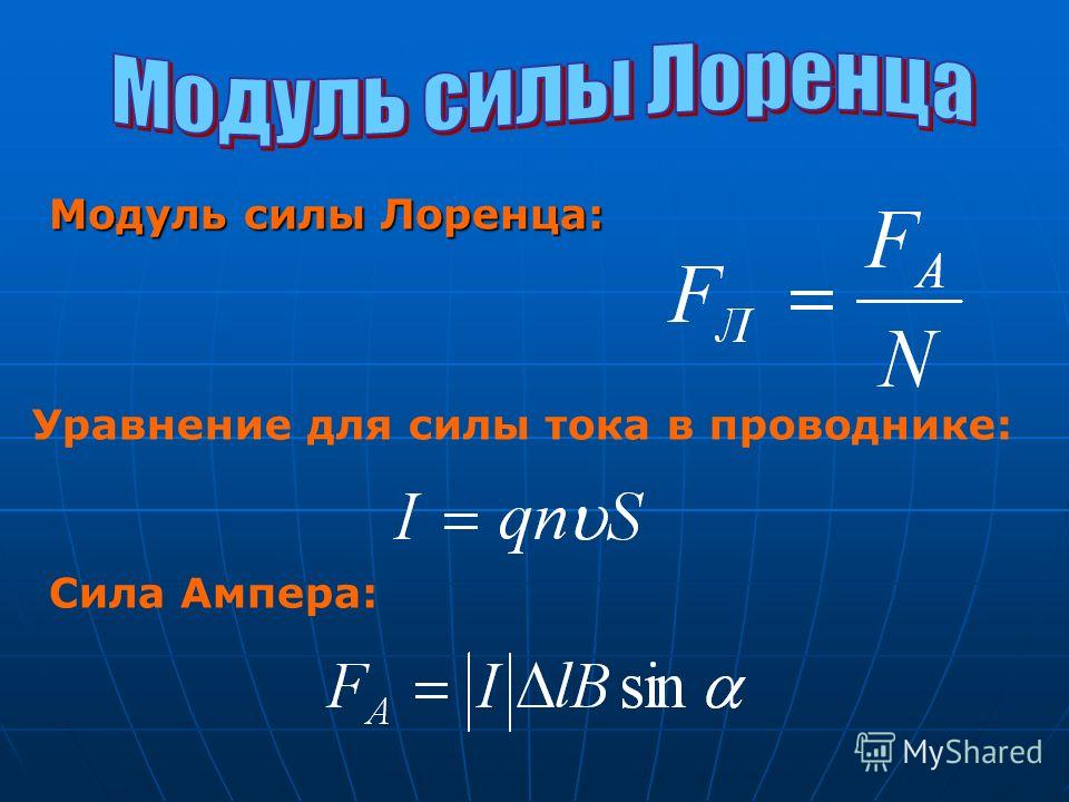
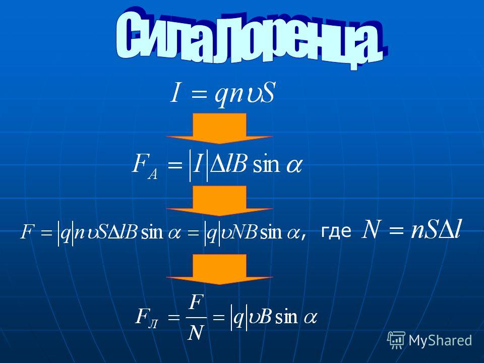
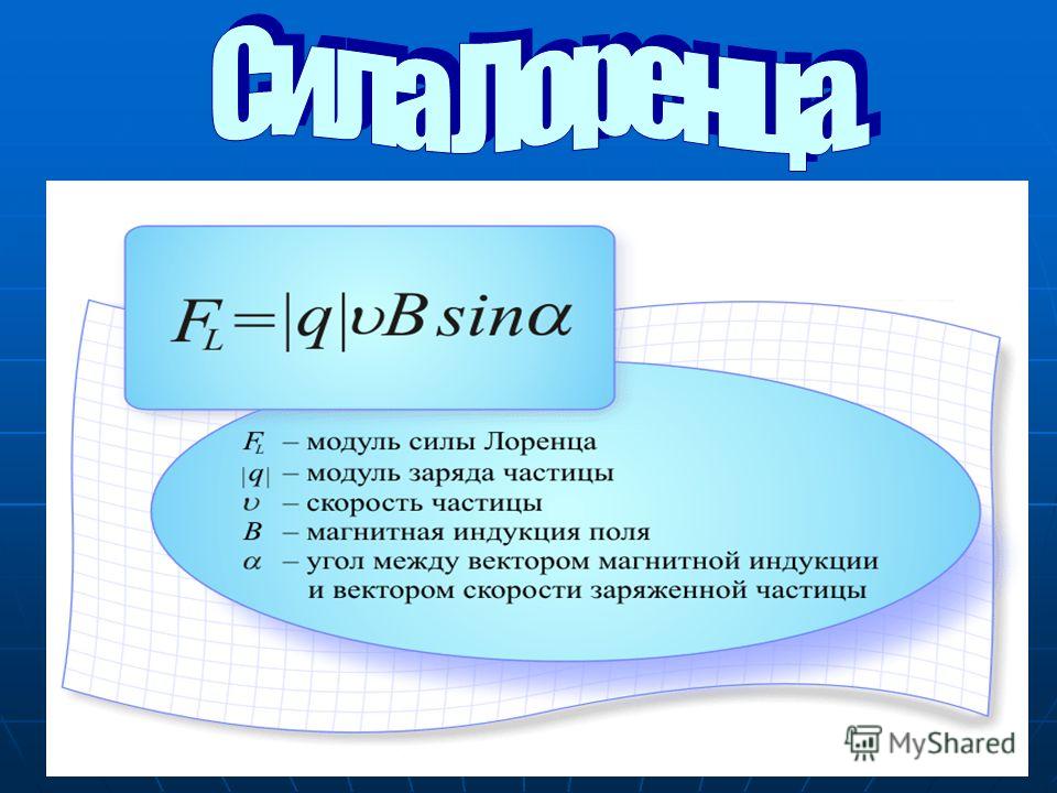
The Lorentz force is a force acting on a moving charged particle from the side magnetic field. H. Lorenz () – Dutch physicist, founder of the electronic theory of the structure of matter.

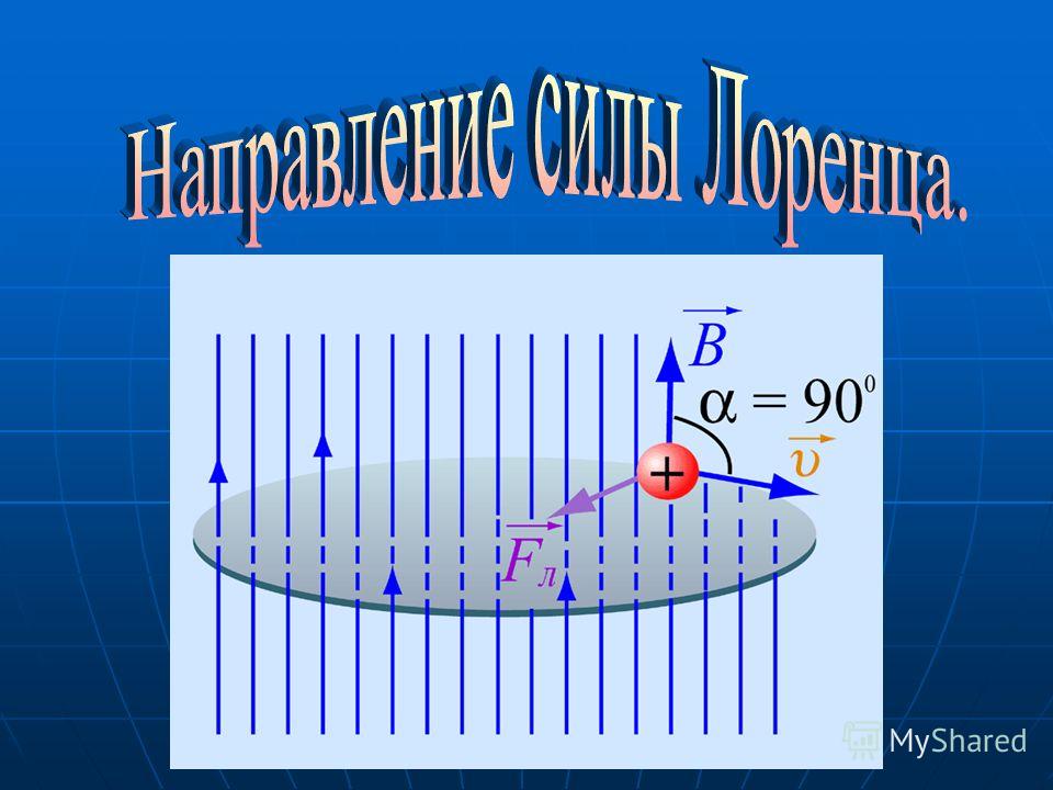

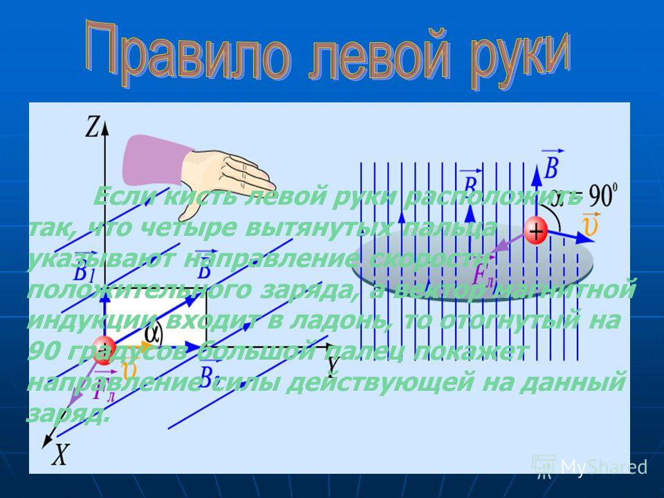
If the left hand is positioned so that four extended fingers indicate the direction of the velocity of the positive charge, and the magnetic induction vector enters the palm, then the thumb bent 90 degrees will indicate the direction of the force acting on this charge.
Flat trajectories of charged particles in a uniform magnetic field A charged particle flying into a uniform magnetic field parallel to the magnetic induction lines moves uniformly along these lines. The rotation of a negative charge around a circle occurs in the direction opposite to the rotation of a positive charge (Fig. c)

1. How, knowing the Ampere force, can you find the Lorentz force? 2. Define the Lorentz force. What is its modulus? 3. How is the direction of the Lorentz force determined using the left-hand rule? 4. Why does a charged particle flying into a uniform magnetic field in a plane, perpendicular to the lines of magnetic induction, move in a circle? In what case does a particle move rectilinearly in a magnetic field? 5. Prove that the period of revolution of a charged particle in a transverse magnetic field does not depend on its speed.

In physics and electrical engineering, various techniques and methods are widely used to determine one of the characteristics of a magnetic field - the direction of intensity. For this purpose, the law of the gimlet, right and left hands is used. These methods allow you to obtain fairly accurate results.
Gimlet and right hand rule
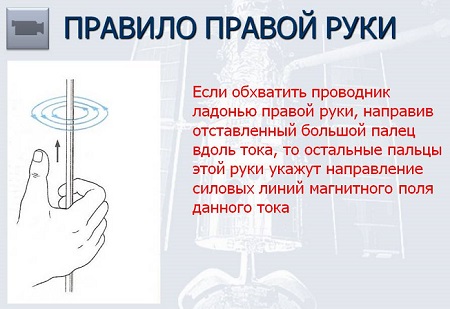
The gimlet's law is used to determine the direction of magnetic field strength. It works under the condition that the magnetic field is located in a straight line relative to the current-carrying conductor.
This rule consists in the coincidence of the direction of the magnetic field with the direction of the handle of the gimlet, provided that the gimlet with a right-hand thread is screwed in in the direction electric current. This rule also applies to solenoids. In this case, the thumb extended on the right hand indicates the direction of the lines. In this case, the solenoid is grasped so that the fingers indicate the direction of the current in its turns. A prerequisite is that the length of the coil exceeds its diameter.
The right hand rule is the opposite of the gimlet rule. When grasping the element under study, the fingers in a clenched fist indicate the direction magnetic lines. In this case, the translational movement in the direction of the magnetic lines is taken into account. The thumb, which is bent 90 degrees relative to the palm, indicates direction.
When the conductor is moving, power lines enters the palm perpendicularly. The thumb is extended perpendicularly and indicates the direction of movement of the conductor. The remaining four protruding fingers are located in the direction of the induction current.
Left hand rule
Among such methods, as a rule, the gimlet rule, the right and left hands, the left hand rule should be noted. In order for this rule to work, it is necessary to position the left palm in such a way that the direction of the four fingers is towards the electric current in the conductor. The induction lines enter the palm perpendicularly at an angle of 900. The thumb is bent and indicates the direction of the force acting on the conductor. Typically, this law is applied when it is necessary to determine the direction of deflection of a conductor. In this situation, a conductor is located between two magnets and an electric current is passed through it.

The left hand rule is also formulated in such a way that the four fingers on the left hand are located in the direction in which positive or negative particles of electric current move. The induction lines, as in other cases, should be perpendicular to the palm and enter into it. The protruding thumb indicates the direction of the Ampere or Lorentz force.
A magnetic field acts on a current-carrying conductor. The force that arises in this case is called Ampere force.
Ampere power acts on a conductor with current in a magnetic field.
Let's explore what the modulus and direction of this force depend on. For this purpose, we use a setup in which a straight conductor is suspended on thin wires in a magnetic field permanent magnet(Fig. 6.16). Flexible wires attached to the ends of the conductor allow it to be included in an electrical circuit, the current in which is regulated using a rheostat and measured with an ammeter.
A light but rigid pull connects the conductor to the sensitive force meter.
Having closed the electrical circuit into which the conductor under study enters, we will see that it will deviate from the equilibrium position, and the meter will show a certain force value. Let us increase the current in the conductor by 2 times and see that the force acting on the conductor will also increase by 2 times. Any other changes in the current strength in the conductor will cause corresponding changes in the force that acts on the conductor. A comparison of the results obtained allows us to conclude that the strength F, acting in a magnetic field on a current-carrying conductor is proportional to the current strength I in him:
Ampere power proportional to the current strength in the conductor.
Let's place another magnet next to the first one. The length of that part of the conductor that is in the magnetic field will increase approximately 2 times. The force acting on the conductor will also approximately double. Thus, the power F, acting on a conductor with current in a magnetic field, proportional to the length of the conductor part Δ l, which is in a magnetic field:
F~Δ l.
Ampere power proportional to the length of the active part of the conductor.
The force will also increase when we use another, “stronger” magnet with greater magnetic induction. This allows us to draw a conclusion about the dependence of the force F from magnetic field induction B:
F~B. Material from the site
The maximum force will be when the angle α = 90° between the magnetic induction and the conductor. If this angle equal to zero, that is, the magnetic induction will be parallel to the conductor, then the force will be zero. From here it is easy to draw a conclusion about the dependence Ampere forces from the angle between the magnetic induction and the conductor.
The final formula for calculation Ampere forces will look like
F A= BIΔ l. sin α .
Direction Ampere forces determined by the rule left hands (Fig. 6.17).
Left hand rule. If left hand placed so that the lines of magnetic induction enter the palm, and four fingers show the direction of the current, then the outstretched thumb will show the direction of the force acting on the conductor with the current in the magnetic field.