An acoustic wave is a consequence of a physical phenomenon called sound. AB propagates in the form of pure mechanical vibrations under various physical conditions.
Magnons, as waves are also called, are considered vibrations perceived by our senses. Of course, animals are also capable of perceiving sounds. Let us consider in more detail the nature of acoustic waves and their varieties.
General audio considerations
Sound is magnon. Like any material phenomenon, it is qualified by the frequency of movement and the spectrum of frequencies. You and I are able to distinguish noise vibrations in the frequency range ranging from 16Hz to 20kHz.

Note. It will be interesting to know that sound emissions below the range of normal human audibility are usually called infrasound, and those above are called ultrasound or hypersound. The difference between ultrasound and hypersound depends on GHz. The first implies a value up to 1 GHz, the second – from 1 GHz.
We are interested in musical sounds, but in fact, sound can also be phonetic, speech and phonemic. Melodic sound emissions include several different tones. Consequently, the noise in such sound emissions can vary over a wide frequency range.
AB is a striking example of an amplitude process. And, as is known, any change is associated with an imbalance of the system and is formulated in the tolerance of its parameters. In a word, AB are variable zones of contraction and expansion.

Let's look at this physical phenomenon otherwise. Alternation in this case implies a change in pressure, which is initially transmitted to neighboring particles. The latter continue to transmit vibrations to the next particles and so on. Note that after the high pressure spectrum there is a zone of low pressure.
AB, as mentioned above, spreads in various physical environments:
- In airlift (gas);
- In liquid;
- In solid.
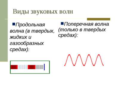
In the first 2 media, AB have longitudinal vibrations, which is explained by the absence of significant vibrations associated with density. In other words, in such an environment, vibrations intersect with the course of wave movements.
On the contrary, in a solid medium, in addition to longitudinal deformations AB, shear deformations are also observed, implying the excitation of transverse or shear waves.
Knowledge about sound waves
It will be useful to know that sound radiation or waves are a variety of all types of waves found in our Everyday life. Those magnons that we find in music are usually called sound magnons.
A wave, as such, has neither color nor other usual physical properties, but rather represents a certain state that can be described in physical and mathematical language.
You should also know the following about waves:
- They have properties that can transfer energy from one point to another, like any moving object.
Note. The power of an acoustic wave is clearly visible in the example of a speaker on which something very sensitive is placed. This could be, for example, a sheet of paper with sea or river sand sprinkled on it. The louder the sound, the stronger the vibration and, accordingly, the energy of the wave. She can even create mysterious patterns on a piece of paper by stirring the bouncing grains of sand.
- Linearity is another magnon parameter, manifested in the ability of vibrations of one wave not to affect the vibrations of another. Ideal linearity always implies parallelism;
- A very important pattern of sound waves is reflected in the proper installation of acoustics. Thus, a specialist installer should be aware that the speed of sound propagation is determined not so much by frequency as by the surrounding environment.
Note. It is for this very reason that it is so important to carry out noise and vibration insulation of the car body, to correctly direct the speakers so that the sound is reflected correctly.
- For better perception of a sound wave, there is such a thing as intensity or simply volume. As a rule, the optimal range for hearing is in the range of 1000-4000 Hz.
Standard AB parameters
Let's look at the most common sound parameters:
- Oscillation speed, which is measured in m/s or cm/s;
- Coeff. attenuation, reflecting the rate of decrease in speed with time or S;
- Logarithmic decrement or D, characterizing the decrease in movement speed per cycle;
- Quality factor or Q, which determines the quality factor of the circuit elements through which sound flows;
- Acoustic reactance Z or the ability to move sound energy, including hypersonic;
- Sound pressure or value representing the difference between point pressure and static pressure. Acoustic pressure can also be called variable pressure in a medium caused by sound vibrations. Measured in Pa;
- Travel speed in environment. As a rule, it is less in a gaseous environment, more in a solid;
- Loudness or the perceived intensity of a sound as perceived by each person individually. This parameter depends on the sound pressure, speed and frequency of acoustic vibrations.
Types of AB

Acoustic waves can be superficial or elastic.
Let us first consider surface acoustic waves in detail:
- First of all, they are elastic waves, propagating along the surface of a solid;
- Superficial ABs are, in turn, divided into 2 types: vertical and horizontal (Love waves).
Superficial AVs, in addition, can occur in the following special cases:
- When they propagate along the boundaries of an elastic vacuum half-space;
- When wave attenuation is observed at the boundary of two types of physical media - liquid and solid;
- When an undamped wave having vertical polarization is observed;
- A wave rushing along the flat boundary of solid zones, called Stoneley;
- Surface AV with horizontal polarization, capable of propagating in elastic space.
As for elastic waves, they also propagate in 3 known physical media, but are less related to acoustics as such.
Music has always occupied a person's life great importance. Sound harmony and melody are perceived as something ideal, not implying an ear irritant or ordinary noise.
It will be useful to know that at the end of the 18th century, the famous German scientist E. Hlandi proposed an ingenious method for measuring sound waves. In particular, using the example of the same sheet of sand, the physicist proved that grains of sand form different patterns due to the interference of vibrations. After this, he was able to derive special formulas for calculating sound parameters, which are used by professionals today.
As for the first sound recording, this was accomplished by the great Edison, who conducted experiments with a phonograph at the end of the 19th century. His ingenious system worked based on the pressure of sound waves moving the needle up/down. A sharp piece of metal scratched indentations into the foil material wound around the rotating cylinder.
ACOUSTIC WAVES (sound waves), disturbances of an elastic material medium (gaseous, liquid or solid) propagating in space. Disturbances are local deviations of density and pressure in a medium from equilibrium values, displacements of particles of the medium from the equilibrium position. These changes in the state of the medium, transmitted from one particle of matter to another, characterize the sound field. In acoustic waves, energy and momentum are transferred without transfer of the substance itself.
In gaseous and liquid media, possessing volumetric elasticity, only longitudinal acoustic waves can propagate, in which the displacements of particles coincide in direction with the propagation of the wave. In this case, sound pressure is a scalar quantity. In unlimited solid media, which, in addition to volumetric, also have shear elasticity, along with longitudinal ones, transverse (shear) acoustic waves can also propagate; in them the directions of particle displacement and wave propagation are mutually perpendicular. An analogue of sound pressure in solid media is the mechanical stress tensor. In the presence of boundaries in solids, other types of acoustic waves also arise (see Elastic waves).
In accordance with the type of dependence of the characteristics of the sound field on time, acoustic waves can have different shapes. Of particular importance are harmonic acoustic waves, in which the characteristics of the sound field change in time and space according to a sinusoidal law (see Waves). Acoustic waves of any shape can be represented as a sum (in the limiting case - an integral) of harmonic waves different frequencies. As a result of decomposing the wave into simple harmonic components (see Sound analysis), a sound spectrum is obtained.
The frequency range of acoustic waves from below is practically unlimited - in nature there are acoustic waves with a frequency equal to hundredths and thousandths of a hertz. The upper limit of the range of acoustic waves is due to physical nature their interactions with matter: in gases the wavelength must be greater than the free path of molecules, and in liquids and solids it must be greater than the intermolecular or interatomic distance. On this basis, the value 10 9 Hz is taken as the upper frequency limit in gases, in liquids 10 10 -10 11 Hz, in solids 10 12 -10 13 Hz. In the general range, acoustic waves highlight the region of sound itself, perceived by a person by ear; the conventional boundaries of this region are 16 Hz - 20 kHz (the term “sound” is often applied to acoustic waves throughout the entire frequency range). Below lies the region of infrasound, above - ultrasound (2·10 4 Hz - 10 9 Hz) and hypersound (10 9 Hz - 10 13 Hz). Hypersonic waves in crystals are sometimes considered from the standpoint of quantum theory, comparing them with phonons.
The propagation of acoustic waves is characterized primarily by the speed of sound. Under certain conditions, sound dispersion is observed - the dependence of the speed of acoustic waves on frequency. As the sound propagates, the sound gradually attenuates, i.e., the intensity of the acoustic waves decreases. It is largely due to sound absorption associated with the irreversible transition of acoustic wave energy into heat. The propagation of acoustic waves is considered by the methods of wave acoustics or geometric acoustics. At high intensity of acoustic waves, distortion of their shape and other nonlinear effects are observed (see Nonlinear acoustics).
Sound waves in the audible range serve as a means of communication between people, as well as a wide variety of representatives of the animal world. Acoustic waves are used to obtain information about the properties and structure of different environments and about various objects. With their help, natural environments are studied - the atmosphere, Earth's crust, the World Ocean, the structural features of matter at the microscopic level are clarified. IN practical activities human acoustic waves are used to detect defects in products, are used as one of the methods of medical diagnostics, and are used to influence a substance in order to change its properties.
Lit.: Krasilnikov V. A. Sound and ultrasonic waves in air, water and solids. 3rd ed. M., 1960; Isakovich M. A. General acoustics. M., 1973; Skuchik E. Fundamentals of acoustics: In 2 vols. M., 1976. I. P. Golyamina.
When objects of the material world interact, physical processes occur, accompanied by various physical effects. A physical effect (PE) is understood as a change in any property or parameter of a substance, physical body, environment, field or system (physical body - environment - field, physical body - physical body, physical body - environment, etc.) under the influence of one or two sizes.
To ensure unambiguous interpretation of the concept of FE, the following definition has been adopted: physical effect - this is a pattern of manifestation of the results of interaction between objects of the material world, carried out through physical fields. At the same time, the pattern of manifestation is characterized by consistency and repeatability with the identity of the interaction.
The variety of processes and phenomena that occur in nature is due to four types of interactions: universal gravity, electromagnetic, nuclear and weak interactions. Each type of interaction corresponds to certain physical fields, which have a number of modifications that determine the characteristics of the interaction of material objects. For example, the electric field can be electrostatic, alternating, vortex, etc.
The impact is always directed at some material object.
Impact results– these are effects that appear on objects (or in the space surrounding them) to which certain influences are directed. The results of the impact also include changes in object parameters (size, shape, dielectric constant, etc.). When the interaction conditions and properties of the object are constant, the same results of influence appear.
Generalized diagram of the physical effect can be presented as shown in Fig. 3.1. The model of a physical effect characterizes the dependence of the result of the effect on the impact and should reflect the conditions for the relationship of physical effects with each other, provide a quantitative description of the manifestation of the physical effect, ensure the determination of the results of impacts for given impacts, the values of variable parameters of a physical object, time characteristics, etc.
In general, the FE model has the form
Where C i – parameters i- th result of the impact; A OSN , A DOP– parameters of the main and additional impacts; ( b 1 , b 2 , b n) – tuple of parameters of a physical object ; t– time characterizing the manifestation of a physical effect.
For many physical objects, strict mathematical relationships between the impact and the result of the impact are not yet known. In this case, empirical dependencies or experimental data are used.
Depending on the nature of the result of the impact, physical effects can be divided into PE: 1) with electrical ones; 2) magnetic; 3) thermal; 4) mechanical; 5) optical; 6) chemical; 7) radioactive; 8) spatial; 9) temporary results of exposure.
Let's consider some physical effects that have found wide application in various fields of technology, in particular in the measurement and control of various physical quantities and objects.
Introduction
Elasticity is the property of solids to restore their shape and volume (and liquids and gases - only volume) after the cessation of external forces. A medium that has elasticity is called an elastic medium. Elastic vibrations are vibrations of mechanical systems, an elastic medium or its part, arising under the influence of mechanical disturbance. Elastic or acoustic waves are mechanical disturbances propagating in an elastic medium. A special case of acoustic waves is the sound heard by humans, hence the term acoustics (from the Greek akustikos - auditory) in the broad sense of the word - the study of elastic waves, in the narrow sense - the study of sound. Depending on the frequency, elastic vibrations and waves are called differently.
Table 1 - Frequency ranges of elastic vibrations
Elastic vibrations and acoustic waves, especially in the ultrasonic range, are widely used in technology. Powerful low-frequency ultrasonic vibrations are used for local destruction of fragile, durable materials (ultrasonic chiselling); dispersion (fine grinding of solid or liquid bodies in any medium, for example fats in water); coagulation (enlargement of particles of a substance, for example, smoke) and other purposes. Another area of application of acoustic vibrations and waves is control and measurement. This includes sound and ultrasonic location, ultrasonic medical diagnostics, control of liquid level, flow rate, pressure, temperature in vessels and pipelines, as well as the use of acoustic vibrations and waves for non-destructive testing (NDT).
In his test work I plan to consider acoustic methods for testing materials, their types and features.
1. Types of acoustic waves
Acoustic testing methods use low amplitude waves. This is the region of linear acoustics where stress (or pressure) is proportional to strain. The region of oscillations with large amplitudes or intensities, where such proportionality is absent, refers to nonlinear acoustics.
In an unbounded solid medium, there are two types of waves that propagate at different speeds: longitudinal and transverse.
Rice. 1 - Schematic representation of longitudinal (a) and transverse (b) waves
Wave u l called longitudinal a wave or an expansion-compression wave (Fig. 1.a), because the direction of oscillations in the wave coincides with the direction of its propagation.
Wave u t called transverse or a shear wave (Fig. 1. b). The direction of vibrations in it is perpendicular to the direction of propagation of the wave, and the deformations in it are shear. Transverse waves do not exist in liquids and gases, since in these media there is no elasticity of shape. Longitudinal and transverse waves (their general name is body waves) most widely used for materials inspection. These waves best detect defects when incident normally on their surface.
Distribute along the surface of a solid body surface (Rayleigh waves) and head (creeping, quasi-homogeneous) waves .
Rice. 2 - Schematic representation of waves on the free surface of a solid body: a - Rayleigh, b - head
Surface waves are successfully used to detect defects near the surface of a product. It selectively reacts to defects depending on the depth of their occurrence. Defects located on the surface give maximum reflection, and at a depth greater than the wavelength they are practically not detected.
A quasi-homogeneous (head) wave almost does not react to surface defects and surface irregularities, at the same time, it can be used to detect subsurface defects in a layer, starting from a depth of about 1... 2 mm. The control of thin products by such waves is hampered by lateral transverse waves, which are reflected from the opposite surface of the OC and give false signals.
If two solid media border each other (Fig. 3, c), the moduli of elasticity and density of which do not differ much, then along the boundary propagates Stoneleigh wave(or Stonsley), Such waves are used to control the joining of bimetals.
Transverse waves propagating along the interface between two media and having horizontal polarization are called Love waves. They arise when on the surface of a solid half-space there is a layer of solid material in which the speed of propagation of transverse waves is less than in the half-space. The depth of wave penetration into the half-space increases with decreasing layer thickness. In the absence of a layer, the Love wave in the half-space turns into a volume wave, i.e. into a plane, horizontally polarized, transverse wave. Love waves are used to control the quality of coatings (cladding) applied to the surface.
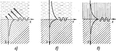
Rice. 3 - Waves at the boundary of two media: a - damped Rayleigh type at the boundary of a solid - liquid, b - weakly damped at the same boundary, c - Stoneley wave at the boundary of two solids
If a solid body has two free surfaces (plate), then specific types of elastic waves can exist in it. They are called waves in plates or Lamb waves and refer to normal waves, i.e. waves traveling (transferring energy) along a plate, layer or rod, and standing(not transferring energy) in a perpendicular direction. Normal waves propagate in a plate, as in a waveguide, over long distances. They are successfully used to control sheets, shells, pipes with a thickness of 3... 5 mm or less.
There is also a special type of waves - ultrasonic waves. By their nature, they do not differ from waves in the audible range and obey the same physical laws. But ultrasound has specific features that have determined its widespread use in science and technology. Reflection, refraction and the ability to focus ultrasound are used in ultrasonic flaw detection, in ultrasonic acoustic microscopes, in medical diagnostics, and to study macro-inhomogeneities of a substance. The presence of inhomogeneities and their coordinates are determined by reflected signals or by the structure of the shadow.
2. Refraction, reflection, diffraction, refraction of acoustic waves
Refraction- the phenomenon of changing the route light beam(or other waves) that occurs at the interface between two transparent (permeable to these waves) media or in the thickness of a medium with continuously changing properties.
Refraction of sound - changing the direction of propagation sound wave when it passes through the interface between two media.
When falling on the interface between two homogeneous media (air - wall, air - water surface, etc.), a plane sound wave can partially reflect and partially refract (pass into the second medium.
A necessary condition for refraction is the difference speed of sound propagation in both environments.
According to the law of refraction, the refracted ray (OL") lies in the same plane with the incident ray (OL) and the normal to the interface drawn at the point of incidence O. Ratio of the sine of the angle of incidence α to the sine of the angle of refraction β equal to the ratio of the speeds of sound waves in the first and second media C 1 And C 2(Snell's law):
sinα/sinβ=C 1 /C 2
From the law of refraction it follows that the higher the speed of sound in a particular medium, the greater the angle of refraction.
If the speed of sound in the second medium is less than in the first, then the angle of refraction will be less than the angle of incidence, but if the speed in the second medium is greater, then the angle of refraction will be greater than the angle of incidence. If specific acoustic impedance If both media are close to each other, then almost all the energy will transfer from one medium to the other.
An important characteristic of a medium is the specific acoustic impedance, which determines the conditions for sound refraction at its boundary. When a plane wave is normally incident on a plane interface between two media, the value of the refractive index is determined only by the ratio of the acoustic impedances of these media. If the acoustic impedances of the media are equal, then the wave passes the boundary without reflection. When the wave is normally incident on the boundary of two media, the transmission coefficient W waves are determined only by the acoustic impedances of these media Z 1 =ρ 1 C 1 And Z 2 =ρ 2 C 2. Fresnel's formula (for normal incidence) is:
W=2Z 2 /(Z 2 +Z 1).
Fresnel formula for a wave incident on the interface at an angle:
W=2Z 2 cosβ/(Z 2 cosβ+Z 1 cosα).
SOUND REFLECTION- a phenomenon that occurs when a sound wave falls on the interface between two elastic media and consists of the formation of waves propagating from the interface into the same medium from which the incident wave came. As a rule, the reflection of sound is accompanied by the formation of refracted waves in a second medium. A special case of sound reflection is reflection from a free surface. Reflection at flat interfaces is usually considered, but we can talk about the reflection of sound from obstacles free form, if the size of the obstacle is significantly larger than the sound wavelength. Otherwise there is sound scattering or sound diffraction.
By measuring the amplitude of the reflected wave, we can estimate the size of the reflecting object.
The amplitude (energy) reflected from the boundary of two media and transmitted to another medium depends on the characteristics of these media. This characteristic is called acoustic resistance (characteristic impedance) and for each medium is described by the expression
where r is the density of the material, and C is the speed of the elastic wave in this material.
The amplitude (energy) of the reflected wave also depends on the shape of the reflecting body and its location relative to the propagating wave. The parameters of the reflected wave are determined by the shape and location of the reflecting body. By examining the parameters of the reflected wave, we can determine the shape of the defect. This is very important for assessing the degree of its danger (usually planar defects such as cracks are more dangerous than round defects - pores).
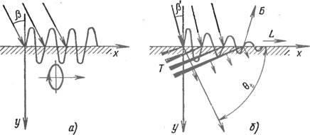
In solids, the pattern of reflection and transmission of elastic waves is more complex. Waves are not only reflected from the interface, but also refracted and transformed (converted from one type to another). What does this mean? In Fig. Figure 4 shows a diagram of a longitudinal wave beam falling at an angle onto the interface between two solid media.
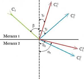
Rice. 4 - Transformation (transformation) of elastic waves when incident on the interface between two materials
It can be seen that not one, but two waves are reflected from the interface. One is longitudinal, and the other is shear (transverse). Moreover, the angle of reflection of the longitudinal wave, as in optics, equal to angle fall of a longitudinal wave.
On the second Wednesday, two waves also pass through. Longitudinal - with an angle different from the angle of incidence, and shear, the angle of which also differs from the angle of reflection of the shear wave in the first solid body. Angles of incidence, reflection and refraction obey Snell's law (law of sines)
From the expression it follows that the angle b is equal to the angle gi, since the speed of propagation in the first medium for the longitudinal wave is the same. We have previously established that the velocities of elastic waves depend on the elastic characteristics of materials and densities. This means that the angles of reflection and refraction also depend on the elastic properties of materials and their densities. At an angle of incidence equal to 90 0, transformation of elastic waves does not occur. In the same time, wonderful property elastic waves reflected from inhomogeneities located inside the material, differing in acoustic (elastic) characteristics, is used to detect defects. All ultrasonic flaw detection, flaw detection, thickness testing, etc. are built on this principle.
Refraction of sound- change in the direction of sound propagation in a heterogeneous medium (atmosphere, ocean, thickness of the earth), the speed of sound in which is a function of coordinates.
Sound refraction (SR) can be considered as a consequence of the effect of wave refraction for cases when the physical properties of the medium continuously change from point to point in the direction of wave propagation. A special case of such a medium is a macro-inhomogeneous structure consisting of many thin homogeneous layers s1, s2, ..., sn, and the speed of propagation of sound waves c varies from layer to layer so that c1 > c2 > ... > cn or c1< c2 < ...< cn. При прохождении волны через границы между соседними слоями имеют место эффекты отражения и преломления волн, в частности, выполняются законы Снеллиуса и соотношения для коэффициентов прохождения и отражения. Результирующей картиной многократного преломления волнового луча в среде c вышеописанными свойствами является изменение направления луча: он искривляется в сторону меньшей скорости звука. При плоско-слоистой неоднородности среды лучи представляют собой плоские кривые, лежащие в плоскостях, перепендикулярных слоям. Согласно закону Снеллиуса, в таких средах выполняется соотношение (cos q)/ c = const, где q - угол скольжения, которое является уравнением луча.
A more general case is the so-called a smoothly inhomogeneous medium in which the speed of propagation of elastic waves is a continuous function of coordinates. Such a medium is not layered because it does not contain contrasting, in the acoustic sense, boundaries at which the classical laws of reflection and refraction are satisfied.
Sound refraction is an important factor influencing the propagation of sound in the atmosphere, ocean, and interior of the Earth. Refractive effects can also be observed during the propagation of ultrasound in products and materials if the speed of sound in them varies along the thickness, for example, due to surface cementation. Therefore, sound refraction is the basis for acoustic methods for monitoring the quality of cementation of massive structures (dams, etc.) and the degree of soil compaction under its own weight and under external loads.
Diffraction (waves bending around obstacles) occurs when the ultrasonic wavelength is comparable (or greater) to the size of the obstacle in the path. If the obstacle is large compared to the acoustic wavelength, then there is no diffraction phenomenon. When several ultrasonic waves move simultaneously in tissue at a certain point in the medium, a superposition of these waves can occur. This superposition of waves on each other carries common name interference. If, in the process of passing through a biological object, ultrasonic waves intersect, then at a certain point in the biological environment an increase or decrease in vibrations is observed. The result of interference will depend on the spatial relationship of the phases of ultrasonic vibrations at a given point in the medium. If ultrasonic waves reach a certain area of the medium in the same phases (in phase), then the particle displacements have the same signs and interference under such conditions helps to increase the amplitude of ultrasonic vibrations. If ultrasonic waves arrive at a specific area in antiphase, then the displacement of particles will be accompanied different signs, which leads to a decrease in the amplitude of ultrasonic vibrations.
3. Reception and emission of ultrasound
Ultrasound is elastic vibrations and waves with frequencies from approximately 1.5-2 × 10⁴ Hz (15-20 kHz) and up to 109 Hz (1 GHz), the ultrasound frequency range from 109 to 1012-13 Hz is usually called hypersound. The frequency range of ultrasound can be divided into three sub-regions: ultrasound low frequencies(1.5×10⁴-105 Hz) - ULF, mid-frequency ultrasound (105 - 107 Hz) - USF and high-frequency ultrasound region (107-109 Hz) - UHF.
To generate Ultrasonic vibrations are used by a variety of devices, which can be divided into 2 main groups - mechanical (the source of ultrasound is the mechanical energy of a gas or liquid flow) and electromechanical (ultrasonic energy is obtained by converting electrical energy). Mechanical ultrasound emitters - air and liquid whistles and sirens - are distinguished by their comparative simplicity of design and operation and do not require expensive electrical energy high frequency, their efficiency is 10-20%. The main disadvantage of all mechanical ultrasonic emitters is the relatively wide range of emitted frequencies and the instability of frequency and amplitude, which does not allow their use for control and measurement purposes; They are used mainly in industrial ultrasonic technology and partly as signaling devices.
The main method of ultrasound radiation is the transformation of electrical vibrations into mechanical vibrations in one way or another. In the ULF range it is possible to use electrodynamic and electrostatic emitters. Ultrasound emitters using the magnetostriction effect in nickel and a number of special alloys, also in ferrites, have found wide application in this frequency range. For USCh and ultrasonic frequency radiation, the phenomenon of piezoelectricity is mainly used. The main piezoelectric materials for ultrasound emitters are piezoquartz, lithium niobate, potassium dihydrogen phosphate, and in the ULF and USF ranges - mainly various piezoceramic materials. Magnetostrictive emitters are a rod- or ring-shaped core with a winding through which flows alternating current, and piezoelectric - a plate (Fig. 5) or a rod made of piezoelectric material with metal electrodes to which an alternating electrical voltage is applied. In the ULF range, composite piezo emitters in which a piezoceramic plate is clamped between metal blocks have become widespread.
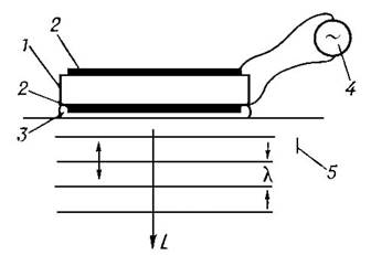
Rice. 5 - Emission (reception) of longitudinal waves L by a plate oscillating in thickness into a solid: 1 - quartz slice plate X with thickness l/2, where l is the wavelength in quartz; 2 - metal electrodes; 3 - liquid (transformer oil) for making acoustic contact; 4 - generator of electrical oscillations; 5 - solid
The maximum intensity of ultrasound radiation is determined by the strength and nonlinear properties of the material of the emitters, as well as the peculiarities of the use of the emitters. The intensity range for ultrasound generation in the USF region is extremely wide: intensities from 10-14-10-15 W/cm 2 to 0.1 W/cm 2 are considered low. For many purposes it is necessary to obtain much higher intensities; in these cases, focusing ultrasound can be used.
The choice of ultrasound generation method depends on the ultrasound frequency range, the nature of the medium (gas, liquid, solid), the type of elastic waves and the required radiation intensity.
Due to the reversibility of the piezoelectric effect, it is widely used for ultrasound reception. The study of the ultrasonic field can also be carried out using optical methods: ultrasound, propagating in any medium, causes a change in its optical refractive index, due to which it can be visualized if the medium is transparent to light.
4. Ultrasound in various environments
Ultrasonic waves propagate only in a material medium. They are characterized by wavelength, frequency (f) and propagation speed (C). The wavelength is expressed as the ratio of the propagation speed to the oscillation frequency.
The frequency boundary between sound and ultrasonic waves is therefore arbitrary; it is determined by the subjective properties of human hearing and corresponds to the averaged upper limit of audible sound. However, due to higher frequencies and, therefore, short wavelengths, a number of features of ultrasound propagation occur. Thus, for ultrasonic waves, the wavelengths in air are 3.4․10 -3 -3.4․10 -5 cm, in water 1.5․10 -2 -1.5․10 -4 cm and in steel 5․10 -2 - 5․10 -4 cm. Ultrasonic vibrations in the low-frequency range will be closer in their physical properties to sounds, high-frequency ultrasounds have features that are not characteristic of sounds. The frequency response and wavelength largely determine the characteristics of the propagation of vibrations in the environment. If low-frequency ultrasounds have the ability to propagate in air environment, then high-frequency ultrasounds practically do not propagate in the air.
Ultrasound in gases and, in particular, in air propagates with high attenuation. Liquids and solids (especially single crystals) are, as a rule, good conductors of ultrasound, in which the attenuation is much less. For example, in water, the attenuation of ultrasound, other things being equal, is approximately 1000 times less than in air. Therefore, the areas of use of ultrasonic frequency and ultrasonic frequency refer almost exclusively to liquids and solids, and in air and gases only ultrasonic frequency is used. Due to the short wavelength of ultrasound, the nature of its propagation is affected by the molecular structure of the medium, therefore, by measuring the ultrasound speed c and the absorption coefficient α, one can judge the molecular properties of the substance. Feature propagation of ultrasound in gases and liquids - the existence of clearly defined areas of dispersion, accompanied by a sharp increase in its absorption. The absorption coefficient of ultrasound in a number of liquids significantly exceeds that calculated by classical theory and does not show the increase predicted by this theory, proportional to the square of the frequency. All these effects are explained in the relaxation theory, which describes the propagation of ultrasound in any media and is the theoretical basis of modern molecular acoustics, and the main experimental method is measuring the dependence of c and especially α on frequency and on external conditions (density, elasticity, viscosity, temperature and etc.). So, for example, when the air temperature increases by 1°, the speed increases by 0.5 m/s.
5. Reflection and scattering of ultrasound
Ultrasound reflection occurs at the interface between media with different acoustic impedances (complex resistance, which is introduced when considering vibrations of acoustic systems). The magnitude of ultrasound reflection is directly proportional to the difference in acoustic impedance of the media. Ultrasound is reflected from objects whose dimensions are at least 1/4 of the wavelength. The angle of incidence of ultrasound is equal to the angle of reflection. The closer the angle of incidence is to 90 degrees, the greater the magnitude of the reflected ultrasound. The quality of its visualization, mainly the contrast of the image, depends on the ability of the tissue to reflect. Reflectance coefficient (RC) is determined by the ratio of the acoustic impedances of two adjacent tissue media. Depending on the ratio of the wavelength of the probing radiation and the size of the reflection objects, three types of reflectors are distinguished:
I) Single reflectors whose dimensions are smaller than the wavelength. They reflect ultrasound in accordance with the Rayleigh theory of diffuse scattering in all directions. The amplitude of signals coming from diffuse reflectors is insignificant.
II) Reflectors whose dimensions are commensurate with the wavelength. In this case, the amplitude of the echo signals increases.
III) Mirror reflectors, the dimensions of which are much larger than the wavelength. In this case, the reflection becomes directional, and the amplitude of the echo signals increases even more. In real biological environments All three types of reflectors are usually present.
If there are inhomogeneities in the medium, then sound scattering occurs, which can significantly change the simple propagation pattern of ultrasound and, ultimately, also cause the wave to attenuate in the original direction of propagation.
6. Acoustic methods in non-destructive testing
For the acoustic method of non-destructive testing, vibrations of the ultrasonic and sound ranges with a frequency from 50 Hz to 50 MHz are used. The intensity of vibrations is usually low, not exceeding 1 kW/m2. Such oscillations occur in the region of elastic deformations of the medium, where stress and deformation are related by a proportional relationship (the region of linear acoustics).
In addition to elasticity in volume, in solid body There is elasticity in shape, so waves of two types can propagate in the body: longitudinal and transverse. Acoustic waves in solids are characterized by either displacement, vibrational velocities, or strain or stress tensors.
For control, different types (modes) of waves are used, differing in the direction of particle oscillations, propagation speed and other characteristics.
In the volume of a solid body, as mentioned above, longitudinal and transverse waves can propagate. In a longitudinal wave, the oscillatory velocities of the particles of the medium coincide with the direction of propagation of the wave; in a transverse wave, they are perpendicular to it.
There are many known acoustic methods of non-destructive testing (Fig. 5), some are used in several variants. They are divided into two large groups - active and passive methods.
Active methods are based on the emission and reception of elastic waves, passive methods are based only on the reception of waves, the source of which is the controlled object itself.
Active methods are divided into transmission, reflection, combined (using both transmission and reflection), impedance and natural frequency methods.
Passage methods (Fig. 6) use emitting and receiving transducers located on different or on the same side of the controlled product. Pulsed or (less often) continuous radiation is used and the signal passing through the controlled object is analyzed.
Passage methods include:
1. amplitude shadow method;
2. temporary shadow method;
3. velocimetric method.

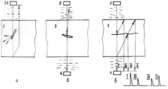
Rice. 6 - Passage methods: a - shadow; b - temporary shadow; c – velosymmetric: 1 – generator; 2 - emitter; 3 - object of control; 4 - receiver; 5 - amplifier; 6 - amplitude meter; 7 - travel time meter; 8 - phase meter
Reflection methods (Fig. 7) use either one or two transducers; pulsed radiation is used. This subgroup includes the following flaw detection methods:
1. echo method;
2. echo-mirror method;
3. delta method;
4. diffraction-time method;
5. reverberation method.

Rice. 7 - Reflection methods: a - echo; b - echo-mirror; c - delta method; d - diffraction-time; d – reverberation: 1 – generator; 2 - emitter; 3 - object of control; 4 - receiver; 5 - amplifier; 6 - synchronizer; 7 – indicator
Combined methods (Fig. 8) use the principles of both transmission and reflection of acoustic waves:
1. mirror-shadow method;
2. echo-shadow method;
3. echo-through method.
Rice. 8 - Combined methods using transmission and reflection: a - mirror-shadow; b - echo-shadow; c - echo-through: 2 - emitter; 4 - receiver; 3 - object of control
Natural frequency methods (Fig. 9) are based on measuring these frequencies (or spectra) of vibrations of controlled objects. Natural frequencies are measured when both forced and free vibrations are excited in products. Free vibrations usually excited by a mechanical shock, forced - by the influence of a harmonic force of varying frequency.
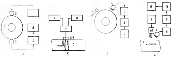
Rice. 9 - Natural frequency methods. Vibration methods: forced: a – integral, b – local; free: c – integral, d – local. 1 - generator of continuous oscillations of varying frequency; 2 - emitter; 3 - object of control; 4 - receiver; 5 - amplifier; 6 - resonance indicator; 7 - frequency modulator; 8 - indicator; 9 - spectrum analyzer; 10 - impact vibrator; 11 - information processing unit
Impedance methods (Fig. 10, a) use the dependence of the impedances of products during their elastic vibrations on the parameters of these products and the presence of defects in them. Passive acoustic methods are based on the analysis of elastic vibrations of waves arising in the controlled object itself. The most typical passive method is the acoustic emission method (Fig. 10, b). The phenomenon of acoustic emission is that elastic waves are emitted by the material itself as a result of internal dynamic local restructuring of its structure. Phenomena such as the appearance and development of cracks under the influence of an external load, allotropic transformations during heating or cooling, and the movement of dislocation clusters are the most typical sources of acoustic emission. Piezoelectric transducers in contact with the product receive elastic waves and make it possible to determine the location of their source (defect).

Rice. 10 - Control methods: a - impedance; b - acoustic emission: 1 - generator; 2 - emitter; 3 - object of control; 4 - receiver; 5 - amplifier; 6 - information processing block with indicator
Passive acoustic methods are vibration diagnostic and noise diagnostic. In the first, the vibration parameters of any individual part or assembly (rotor, bearings, turbine blade) are analyzed using contact-type receivers; in the second, the noise spectrum of a working mechanism is studied, usually using mocrophone receivers.
Based on frequency, acoustic methods are divided into low-frequency and high-frequency. The first include vibrations in the audio and low-frequency (up to several tens of kHz), ultrasonic frequency ranges. The second includes vibrations in the high-frequency ultrasonic frequency range: usually from several hundred kHz to 20 MHz. High frequency methods are usually called ultrasonic.
Conclusion
During the presentation of the material, the achievements of theory and practice in solving various problems of acoustic monitoring were described. The development of acoustic methods occurs along the path of finding new ways to solve the acoustic problems under consideration, namely, the development of methods for emitting and receiving short pulses with a narrow radiation pattern with a reduced requirement for acoustic contact, improving the signal-to-noise ratio when testing materials with a coarse-grained anisotropic structure; achieving high resolution; development of highly informative methods for assessing the shape and size of defects; visual presentation of control results.
Another approach to identifying development trends is based on tasks arising from industry requirements. Here we can name requirements for the control of new materials such as reinforced plastics, metal-ceramics, the creation of highly effective methods for controlling pressure welding, measuring internal stresses in products, guaranteed prediction of the safety of objects, and a number of others.
To solve these problems, they find new methods and methods of control, offer new piezomaterials, expand the mastered frequency range, develop new equipment with increased sensitivity and effective means presenting information, conducting research on radiation, propagation, diffraction of waves, and methods for processing control results.
Literature
1. Brekhovskikh L.M., Godin O.A. Acoustics of layered media. - M.: Nauka, 1989. - 416 p.
2. Viktorov I.A. Ultrasonic surface waves in solids. - M.: Nauka, 1981. - 288 p.
3. Ermolov I.N. Theory and practice of ultrasonic testing. - M.: Mechanical Engineering, 1981. - 240 p.
4. Ivanov V.I., Belov V.M. Acoustic emission control of welding and welded joints. - M.: Mechanical Engineering, 1981. - 284 p.
5. Lange Yu.V. Acoustic low-frequency methods of non-destructive testing of multilayer structures. - M.: Mechanical Engineering, 1991.
6. Methods of acoustic testing of metals / Ed. N.P. Aleshina. - M.: Mechanical Engineering, 1989. - 456 p.
7. Potapov A.I. Quality control and reliability prediction of structures made of composite materials. - L.: Mechanical Engineering, 1980.- 261 p.
8. Instruments for non-destructive testing of materials and products. Directory. In 2 books. / Ed. V.V. Klyueva. - M.: Mechanical Engineering, 1986. Book. 2. - 352 p.
9. Skuchik E. Fundamentals of acoustics. In 2 volumes - M.: Mir, 1976. T. 2. -546 p.
10. Ultrasound. Little Encyclopedia / Ed. A.P. Galyamina. - M.: Soviet Encyclopedia, 1979. - 400 p.
11. Ultrasonic piezoelectric transducers for non-destructive testing / Ed. I.N. Ermolova. - M.: Mechanical Engineering, 1986. - 280 p.
12. Physical acoustics. In 4 vols. Ed. W. Mason. T. 1. Methods and instruments of ultrasound research. C.A. - M.: Mir, 1966. - 592 p.
13. Chebanov V.E. Laser ultrasonic testing of materials. - L.: From date. Leningrad University, 1986. - 232 p.
14. Schreiber D.S. Ultrasonic flaw detection. - M.: Metallurgy, 1965. - 392 p.
Application
1. The property of bodies to restore their shape and volume after the cessation of external forces is...
a) elasticity
b) creep
c) hardness
2. Vibrations of a mechanical system, an elastic medium or its part, arising under the influence of a mechanical disturbance are...
a) mechanical vibrations
b) elastic vibrations
c) cyclical fluctuations
3. Audible sound range
a) below 20 Hz
b) above 10 9 Hz
c) 20-20*10 3 Hz
4. Waves with an oscillation frequency of 20 * 10 3 ... 1 * 10 9 Hz
a) hypersound
c) infrasound
c) ultrasound
5. Wave u l called... a wave or an expansion-compression wave, because the direction of oscillations in the wave coincides with the direction of its propagation.
a) longitudinal
b) transverse
c) Rayleigh
6. Wave u t called ... or shear wave.
a) longitudinal
b) transverse
c) Rayleigh
7. Surface wave is used to detect defects...
a) near the surface of the product
b) in the depth of the product
c) next to the product
8. The main method of ultrasound radiation...
a) conversion of mechanical vibrations into electrical ones
b) conversion of electrical vibrations into light
c) conversion of electrical vibrations into mechanical ones
9. Widely used for ultrasound reception
a) light effect
b) piezoelectric effect
c) multi-effect
10. Ultrasonic waves propagate only in ... medium
a) material
b) intangible
c) interactive
11. Ultrasound propagates in gases...
a) without attenuation
b) with less attenuation
c) with high attenuation
12. Ultrasound reflection occurs at the boundary with... acoustic impedances
a) the same
b) different
c) any
13. For the acoustic method of non-destructive testing, vibrations of the ultrasonic and sound ranges with a frequency of ...
a) 50 Hz – 50 MHz
b) 10 Hz – 10 MHz
c) 100 Hz – 100 MHz
14. Waves can propagate in the body:
a) diagonal and transverse
b) angular and longitudinal
c) longitudinal and transverse
15. Emitting and receiving transducers located on different or one side of the controlled product use...
a) reflection methods
b) passing methods
c) natural frequency methods
16. Passage methods include:
a) amplitude shadow method
b) time shadow method
c) velocimetric method
d) all of the above
17. Pulse radiation is used, both one and two converters are used, in ...
a) reflection methods
b) passing methods
c) natural frequency methods
18. The principles of both transmission and reflection of acoustic waves are used in ...
a) combined methods
b) passing methods
c) natural frequency methods
19.Passive acoustic methods are:
a) methods of reflection and natural frequencies
b) transmission and reflection methods
c) vibration diagnostic and noise diagnostic
20. A change in the direction of propagation of a sound wave as it passes through the interface between two media is...
a) reflection
b) refraction
c) attenuation
21. A phenomenon that occurs when a sound wave falls on the interface between two elastic media and consists of the formation of waves propagating from the interface into the same medium from which the incident wave came - this is ...
a) reflection
b) refraction
c) attenuation
22. A change in the direction of sound propagation in an inhomogeneous medium (atmosphere, ocean, thickness of the earth), the speed of sound in which is a function of coordinates is ...
a) reflection
b) refraction
c) refraction
23. You can determine the shape of a defect by examining the parameters...
a) refracted wave
b) reflected wave
c) incident wave
24. The basis of acoustic methods for monitoring the quality of cementation of massive structures (dams, etc.) and the degree of soil compaction under its own weight and under external loads is...
a) reflection
b) refraction
c) refraction
25. When the ultrasonic wavelength is comparable (or greater) to the size of the obstacle in the path, ...
a) refraction
b) diffraction
c) interference
1.a, 2.b, 3.c, 4.c, 5.a, 6.b, 7.a, 8.c, 9.b, 10.a, 11.c, 12.b, 13. a, 14.c, 15.b, 16.d, 17.a, 18.a, 19.c, 20.b, 21.a, 22.c, 23.b, 24.c, 25.c.