Light beam geometry
Problem 10(Novosibirsk State University). A beam of parallel light rays is incident along the normal to the flat face of a glass prism with a refractive index n and exits the prism at an angle to the original direction of incidence. The apex angle of the prism is very small. Find a corner.
Solution... The geometric configuration that meets the conditions of the problem is shown in the figure. For graphical convenience, the angle is shown not too small. However, we consider it as such and apply the Ray formula, passing through the point A, is not refracted, but for the point B we write down the law of refraction of light: ![]() The angle is also small (this confirms the result), therefore the angle + is also small. We have: n= + whence
The angle is also small (this confirms the result), therefore the angle + is also small. We have: n= + whence
Assignment 11(Lomonosov Moscow State University). At the bottom of a reservoir deep H= 1.2 m is point source Sveta. Find the greatest distance from the source to the point on the surface of the water where the rays go beyond the water. Refractive index of water n = 1,33.
Solution... The designations of the line segments and angles are clear from the figure. It is obvious that a ray going at an angle to the vertical more than will not come out of the water, but will experience a full internal reflection... At the point A, according to the law of refraction, n sin = 1. Apply to the triangle ABC the Pythagorean theorem: l 2 = H 2 + S 2. But ![]() Hence,
Hence,
Self-help assignments
Problem 12. Two flat mirrors make up a dihedral angle of 120 °. A point light source is located in the bisector plane. The distance between the first virtual images of the source is l... What will be the distance between images if the dihedral angle is halved?
Answer. l.
Problem 13. In the block of optical glass with a refractive index, there is a cavity filled with air in the form of a plane-parallel plate 0.2 cm thick. A light beam falls on the glass-air interface at an angle of 30 °. Determine the offset of the beam after passing through the air cavity.
Answer... 0.2 cm. 
Assignment 14(Lomonosov Moscow State University). The light beam falls normally on the front face of the glass prism. Refractive angle of the prism = 30 °. What should be the refractive index of the glass in order for the angle of deflection of the beam by the prism to be equal?
Answer... 2cos = 1.73 at< 45°.
Assignment 15(MIPT, 1975). Plano-convex thick lens with radius of curvature of the convex part R= 2.5 cm  made of glass with a refractive index n= 1.5. Where is the focus of such a lens? The angles of refraction are considered small.
Answer... On distance ![]() from the center of the spherical surface.
from the center of the spherical surface.
Assignment 16(MSTU. Bauman). Half a ball radius r= 2 cm, made of glass with  a parallel beam of rays falls by the refractive index. Determine the radius of the bright spot on a screen located at a distance L= 4.82 cm from the center of the ball.
Answer. ![]()
Problem 17. At what distance from the center of the glass sphere with radius R must there be an ant for its image behind the ball to be of life size? Refractive index of glass n.
Answer.
Assignment 18(Lomonosov Moscow State University). The light beam hits the surface of the glass ball. Angle of incidence = 45 °, refractive index of glass Find the angle between the incident ray and the ray exiting the ball.
Answer. ![]()
Assignment 19(Faculty of Chemistry, Lomonosov Moscow State University). A thin beam of light falls normally on the glass hemisphere with a radius R= 30 cm with refractive index n= 4/3. Determine the distance x from the convex surface of the hemisphere to the point at which this bundle will be collected.
Direct a parallel beam of rays?
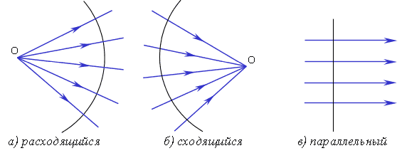
If a beam of rays parallel to the main optical axis is directed to a concave mirror, then all the reflected rays will intersect at one point F 1, which is called the main focus of the concave mirror(fig. 3.2, a).
If a beam of rays parallel to the main optical axis is directed to a convex mirror, then the reflected rays form a diverging beam, but continuation of reflected rays intersect at one point F 2, which is called the main focus of a convex mirror(fig. 3.2, b).
Distance F from pole to main focus is called focal length of a spherical mirror.
It has been experimentally established that the focal length for both concave and convex mirrors is equal to:
where R Is the radius of the mirror.
Practical conclusions. A concave mirror can be used to make fire. Indeed, if you place a concave mirror under a beam of sunlight so that its main optical axis is directed to the Sun, then after reflection, the sun's rays will be collected at the main focus of the mirror. If you place any flammable object, such as a piece of black paper or blown out photographic film, into the main focus of the mirror, then after a while this object will light up. (Do not believe me - check it out experimentally!)
Reader: What happens if a point light source is placed at the main focus of a concave mirror?
Reader: This ray will become incident, and the angle of incidence will be equal to a. Then the angle of reflection will also be equal to a, which means that the reflected ray will coincide with the incident one (Fig. 3.3, b).
 Rice. 3.3
Right. Moreover, this is true for any shape reflective surface: flat, spherical or otherwise. But then it turns out that the beam, sent in the opposite direction, moves along the same trajectory as the beam, going in the forward direction. This statement is a special case of the principle of reversibility (or reciprocity) of light rays, which we will talk about later. For now, let's get back to our question.
If the source is in the main focus of the concave mirror. then, according to the principle of reversibility of light rays, the rays reflected from the mirror form a parallel beam. V ideally the thickness of this beam should not change with distance from the mirror. This means that by directing such a beam at an object located at a large distance from the mirror (say, 1 km), we should see a bright spot on this object, the size of which is equal to the size of our mirror.
In fact, this, of course, will not work, since it is impossible to create either a point light source or an ideal spherical mirror. But slightly divergent You can create a beam of light using a concave mirror. To do this, it is enough to place an electric incandescent lamp in the focus of a concave mirror.
If you take a large mirror with a good reflective surface and a lamp with a power of several thousand watts, you get a fairly powerful spotlight, which will "beat" (brightly illuminate objects) at a distance of several kilometers (Fig. 3.4).
The most important manifestation of Fermat's principle in practice occurs in a situation where the principle of minimum time for a light to travel from one point to another is satisfied by many rays / trajectories. This situation we face in imaging optical systems ... Determination of the shape and position of a set of optical elements giving a high-quality imaging system is the main task geometric optics.
If a beam of light rays emanating from a point P, as a result of the passage of the system, converges at a point P ", then P" is called point image P. Point P "is also called the focal point of geometric convergence. Image P" is called valid if the rays really intersect at point P ". If at point P" the extensions of rays drawn in the direction opposite to the propagation of light intersect, then the image is called imaginary ... If the rays strictly intersect at point P ", then the image is called stigmatic ... Examples of such imaging systems are an ellipsoidal reflector and a double hyperbolic lens.
Usually in optics they deal with spherical surfaces, since they are much easier to manufacture. However, these surfaces do not provide stigmatic images.
Homocentric and non-homocentric ray beams
Homocentric ray beams have a common center, that is, all rays go out or converge at one point and can be converging, diverging, or parallel.
 Homocentricbeams of rays.
Beam focus - this is the point at which all rays converge or from which they all go out. Focus can be imaginary or real. The real focus is formed by the rays themselves, and the imaginary one - by their extensions.
|
|
|
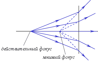
Geometric wavefront is a surface, the normal to which at each point is directed along the ray intersecting this surface at this point. The wavefront of a homocentric beam is a spherical surface / plane. Focus can be imaginary or real. The real focus is formed by the rays themselves, and the imaginary one - by their extensions. These cases are realized when a parallel beam passes through a focusing and diffusing lens.
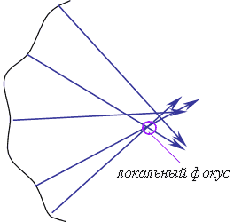
Non-homocentric beam Is a beam that does not have a common focus (rays do not intersect at one point). The wavefront of such a beam is neither spherical nor flat. In most cases, each infinitesimal section of the wavefront is characterized by two main radii of curvature and, therefore, two centers of curvature. So caustic, which is the locus of the principal centers of curvature , is a two-sheet surface.
Brief description of aberrations
Usually, optical systems when constructing images show a number of distortions the resulting image, called aberrations ... Distinguish monochromatic aberration and chromatic aberration ... Chromatic aberration is characteristic of lenses with variance , and manifests itself when exposed to radiation with a wide spectral composition. Mirror elements do not have this aberration.
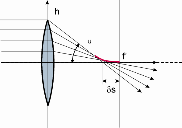
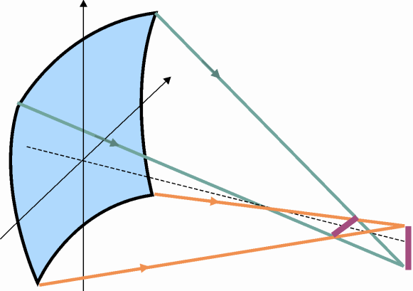
A real lens has a finite thickness, and rays passing through it can be located far from the axis. Let us consider the case of a lens illuminated by a parallel light beam, which occurs when laser radiation is focused by the lens of a laser technological installation. As a result, in a plane perpendicular to the lens axis and passing through its paraxial focus, instead of a stigmatic image, a blurry spot will be obtained. This effect is called spherical aberration because rays striking the lens at large distances from the axis are refracted more strongly and cross the axis closer to the lens than paraxial rays (paraxial focus). The picture shows in red caustic section .
|
|
|
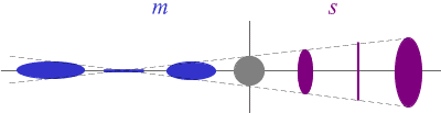
Another important type of monochromatic aberration is astigmatism arising from oblique incidence of beams on lenses or mirrors. Astigmatic beam - special case non-homocentric beam. The distance between the points of convergence of the beams in planes with principal radii of curvature is called astigmatic difference ... The best "point" of the image is located between these segments.
The set of image points when depicting an object is called image surface ... Even if astigmatism is eliminated, there will still be an aberration called image curvature : The image surface is not flat.
Distortion - This is an aberration characterized by the fact that the magnification across the field of view is not the same. This type of aberration causes the image to be “pincushion” or “barrel-shaped” —in the image, straight lines are curved.
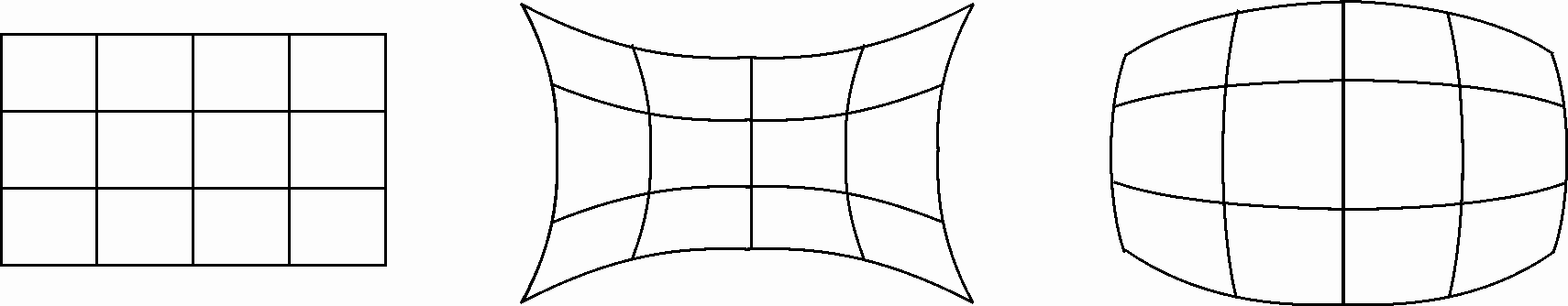
If the magnification increases with distance from the axis, then the rectangular mesh turns into a "pillow". If the increase decreases with distance from the axis, then the rectangular mesh turns into a "barrel".
Finally, the last type of monochromatic aberration is coma ... An off-axis point of an object, when displayed with a wide beam, in this case has an image similar to a tailed comet.
Lesson number 74-75 Diffraction of light. A normally parallel beam is incident on the diffraction grating white light... A lens is located between the grating and the screen, close to the grating, which focuses the light passing through the grating onto the screen. What is the number of lines per cm, if the distance to the screen is 2 m, and the width of the spectrum of the first order is 4 cm. The lengths of the red and violet waves are 800 nm and 400 nm, respectively. Consider that sin? ? tg? 38.
Picture 169 from the presentation "The phenomenon of light diffraction" to physics lessons on the topic "Diffraction"Dimensions: 960 x 720 pixels, format: jpg. To download a picture for free physics lesson, right-click on the image and click "Save Image As ...". To show pictures in the lesson, you can also download the presentation "The Phenomenon of Light Diffraction.ppt" for free with all pictures in a zip-archive. The archive size is 4741 KB.
Download presentationDiffraction
"Diffraction of Mechanical Waves" - The edges of obstacles. Light diffraction. Diffraction pictures. The limits of applicability of geometric optics. Diffraction grating. The dimensions of the obstacle. Diffraction spectra. Diffraction of mechanical waves. Diffraction. Examples of light diffraction. Diffraction patterns from various obstacles. Huygens-Fresnel principle.
"Diffraction of light Huygens principle" - Under what condition is diffraction most noticeable? What are the conditions for the diffraction minima? Who developed the theory of light diffraction? Discovery of diffraction. Huygens-Fresnel principle. What do the phenomena of interference and diffraction of light prove? Fresnel zones. What is a Fresnel zone? What is Light Diffraction? Minimum conditions for interference from the slit: a * sin? = m?, where m ± 0,1,2,3 ...
"The phenomenon of diffraction of light" - Parallel beam of white light. Diffraction by two slits. Diffraction grating formula. Diffraction spectrum. Total length. The width of the slots. The number of strokes. Flat monochromatic light wave... The phenomenon of deflection of light rays. The total length of the diffraction grating. Sodium spectrum lines. Determine the resolution of the diffraction grating.
"Light Diffraction" - Diffraction of mechanical waves. Diffraction phenomena were well known even in Newton's time. Cases when diffraction is observed brightly: Lesson summary: Applying diffraction Diffraction grating. Plan. Commentary on / on. Diffraction gratings are used to decompose electromagnetic radiation into a spectrum.
"Diffraction" - The validity of the division of the wave front into Fresnel zones has been confirmed experimentally. There is a light spot in the center. 7.1. Huygens-Fresnel principle. Diffraction by a circular hole and disc. Fresnel ruled out the possibility of occurrence. Let us now consider diffraction in more detail. amplifying interference (fig. 7.1).
Wave Diffraction - Try to guess what the diffraction pattern will look like? Investigated the deformation. Will the appearance of the diffraction pattern depend on the wavelength (color)? Italian scientist. Optical path difference From the condition of maximum interference we obtain: The smallest distance from point O to wave surface B is equal to r0.
There are 7 presentations in total
A parallel beam of monochromatic light is polarized in a plane with a given azimuth relative to the plane of incidence when the polarizer rotates.
A parallel beam of monochromatic light from the illuminator falls on a plane-parallel beam splitting plate 5 and is split into two coherent beams.
A parallel beam of monochromatic light falls on a wire 1 mm in diameter, stretched perpendicular to the direction of light propagation. On a screen located perpendicular to the direction of light propagation, at a distance of 1 m from the wire, diffraction fringes are observed, the distance between which is 0 5 mm.
When a parallel beam of monochromatic light with intensity / is incident on a layer of solution with a thickness dl, then some of it is absorbed. When the thickness of the absorbing layer is doubled, the absorption is also doubled.
If you direct a parallel beam of monochromatic light, which in Fig. 6.8 is depicted by lines AB and DE, perpendicular to a series of equally spaced points from each other, most of light will pass without undergoing any changes, but if the distances between the points coincide in order of magnitude with the wavelength of light, some part of the light will undergo diffraction. The diffracted rays will start to interfere, unless the difference in paths traversed by the light rays is zero or an integer number of wavelengths.
In this device, a parallel beam of monochromatic light falls on a plane-parallel glass plate covered on one side with a semitransparent layer of silver. The separated beams fall on two mirrors at zero incidence angles and return to the very places of the translucent plate from which they came out. Each ray that returns from the mirror is re-split on the plate. Part of the light returns to the source, and the other part enters the telescope to the right. As a result, two coherent interfering beams are observed in the pipe's field of view. The figure shows that after the first separation on the semitransparent layer, the beam coming from the mirror opposite the pipe passes twice through a glass plate with a semitransparent layer. Therefore, to ensure equality optical paths a beam from another mirror is passed through a compensation plate, identical to the first, but without a semitransparent layer.
A normally parallel beam of monochromatic light with a wavelength K is incident on the slit.
A normally parallel beam of monochromatic light is incident on the slit. A lens with a focal length of / 200 m behind the slit projects a diffraction pattern on the screen in the form of alternating light and dark stripes. The width of the central light stripe is b 5 0 cm. How should the width of the slit be changed so that the central stripe occupies the entire screen for any width of the latter.
Find the law of attenuation of the intensity of a parallel beam of monochromatic light due to molecular scattering in an ideal gas, the refractive index n of which differs little from unity.
A parallel beam of monochromatic light is normally incident on a narrow slit.
A parallel beam of monochromatic light is normally incident on a narrow slit. Determine the relative intensity of the secondary maxima.
A normally parallel beam of monochromatic light with a wavelength K is incident on a slit of width a6.
A normally parallel beam of monochromatic light with a wavelength λ = 5890 A is incident on a slit 2 μm wide. Find the angles in the direction of which the light minima will be observed.
A normally parallel beam of monochromatic light with a wavelength K is incident on a slit 6K wide.
A parallel beam of monochromatic light with a wavelength λ = 6 μm is normally incident on a screen with a circular aperture of radius r 1 2 mm.
A parallel beam of monochromatic light with a wavelength X 0 5 μm is normally incident on a screen with a circular aperture of radius r 1 5 mm. The observation point is located on the axis of the hole at a distance L 1 5 m from it. Determine: 1) the number of Fresnel zones that fit into the hole; 2) a dark or light ring is observed in the center of the diffraction pattern if a screen is placed at the observation point.
Measuring head 7 is a movable interferometer. A parallel beam of monochromatic light from the illuminator 8 is incident on a plane-parallel beam-splitting plate 9 and is divided into two coherent beams. When the measuring head approaches the surface 6 in the plane of the photomultiplier diaphragm 12, an interference pattern appears and the interference fringes will move. At the moment when the focal plane of the lens of the head coincides with the mirror surface 6, the black band of the interference pattern will overlap the diaphragm 12 and there will be a pulse of maximum amplitude at the output of the PMT.
The Bouguer-Lambert law determines the attenuation of a monochromatic light beam as it passes through an absorbing substance. Let a parallel beam of monochromatic light pass through an absorbing substance.
In this device, a parallel beam of monochromatic light falls on a plane-parallel glass plate covered on one side with a semitransparent layer of silver. The separated beams fall on two mirrors at zero incidence angles and return to the very places of the translucent plate from which they left. Each ray, returned from the mirror, is re-split on the plate. Part of the light returns to the source, and the other part enters the telescope to the right. As a result, two coherent interfering beams are observed in the field of view of the tube. Therefore, to ensure equality of optical paths, a beam coming from another mirror is passed through a compensation plate identical to the first one, without a semitransparent layer.
Suppose that the strokes are drawn in the xy plane perpendicular to the x and y axes. Let us direct a parallel beam of monochromatic light of length K to such a grating. The z axis is directed perpendicular to the plane of the two-dimensional grating.
Diagram of an acousto-optic scale with a reference device | Image of an ultrasonic wave with a laser light source. In phase displacement transformers, the use of acoustic modulation of light makes it possible to convert the displacement of a raster or dashed optical measure into a phase shift of an electrical signal. The construction principle of such a device is shown in Fig. 4.20. A parallel beam of monochromatic light is incident along the normal to the acousto-optic modular /, which is an optically transparent body in which a traveling ultrasonic wave propagates.
The eye can distinguish dark from light, has color perception. The eye can fix the alternation of dark and light stripes behind a slit in an opaque screen, on which a parallel beam of monochromatic light falls. This characteristic picture, comparable to the picture of the passage of waves on the surface of a liquid through a slit in a wall placed in the path of wave propagation, can lead to an analogy and lead to the conclusion that light also represents the propagation of oscillations of something. However, in order to concretize this something, it is not enough just direct sensory perception, but in order to penetrate into the essence of things, an additional mental structure is needed, so that by indirect signs different kinds guess there is light electromagnetic wave... It was not so easy to do, as evidenced by the fact that for a long time the theory of ether oscillations existed in science.