The principle of the simplest (flat) capacitor presented in fig. one.
Fig. 1. The principle of the device flat capacitor.
1 covers
2 dielectric
The capacity of such a capacitor defined by a known formula
Determined by the formula
Using foil liners and a multilayer film dielectric, roll-type capacitors can be manufactured in which the specific storage capacity is approximately in the range from 0.1 J / kg to 1 J / kg or from 0.03 mWh / kg to 0.3 mWh / kg. Due to the low specific storage capacity, capacitors of this kind are not suitable for long-term storage of a significant amount of energy, but they are widely used as sources of reactive power in AC circuits and as capacitive resistances.
Significantly more efficiently, energy can be stored in electrolytic capacitors, the principle of the device of which is shown in Fig. 2.
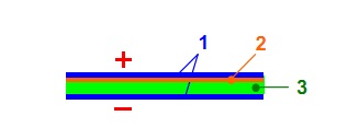
Fig. 2..
1 metal sheet or foil (aluminum, tantalum or others),
2 metal oxide dielectric (Al2O3, Ta2O5 or others),
3 paper, etc., impregnated with electrolyte (H3BO3, H2SO4, MnO2, etc.) and glycerin
Since the thickness of the dielectric layer in this case usually remains within 0.1 µm, these capacitors can be manufactured with a very large capacity (up to 1 F), but at a relatively low voltage (usually a few volts).
May have even greater capacity ultracapacitors (super-capacitors, ionistors), the lining of which is a double electric layer with a thickness of several tenths of a nanometer at the interface between an electrode made of microporous graphite and an electrolyte (Fig. 3).
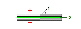
Fig. 3..
1 microporous graphite electrodes,
2 electrolyte
The effective area of \u200b\u200bthe plates of such capacitors reaches, thanks to the porosity, up to 10,000 m2 per gram of electrode mass, which makes it possible to achieve a very large capacity with very small capacitor sizes. Currently, ultracapacitors are available for voltages up to 2.7 V and capacities up to 3 kF. Their specific storage capacity is usually in the range of 0.5 Wh / kg to 50 Wh / kg and there are prototypes with a specific storage capacity of up to 300 Wh / kg.
Manufacturing technology ultracapacitors it is very complex, and the cost per unit of energy stored in them is therefore much higher than that of other capacitors, reaching up to 50,000? / kWh. Despite this, due to the simplicity of design, small size, reliability, high efficiency (95% or more) and durability (several million charge-discharge cycles), they began to be used both in vehicles and in industrial power plants instead of electrochemical batteries and other means of energy storage. They are especially beneficial when energy is consumed in the form of short pulses (for example, to power the starter of internal combustion engines) or when fast (second) charging of the storage device is required. For example, in 2005 in Shanghai, pilot operation of ultracapacitor buses began, the capacitor bank of which is charged while the bus is parked at each stop.
Amber objects can be considered the oldest capacitor and, at the same time, the oldest accumulator of electric energy, the electrification of which during friction with a woolen cloth was discovered by the Greek philosopher Thales around the year 590 H. He also called this phenomenon electronic (from the Greek word electron, ‘amber’). The first electrostatic generators invented in the 17th century also consisted of ball or cylindrical capacitors, on the surface of which an electric charge could accumulate, sufficient to cause discharge phenomena. The first real capacitor is still considered an amplification bottle, invented on October 11, 1745 during experiments on electrifying water by an amateur physicist, Dean of the Cathedral of Cammin (Emin) of the Cathedral Ewald Jurgen von Kleist (1700-1748) (Fig. 4) ;
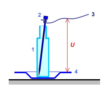
Fig. 4. The condenser Ewald Jürgen von Kleist.
1 bottle filled with water
2 nails, forming the upper lining with water,
3 wire to electrostatic generator,
4 metal plate (bottom plate).
U voltage
With this device, two plates and a dielectric between them can be clearly distinguished. The first flat capacitor was made in 1747 by London doctor John Bevis (John Bevis, 1693–1771), and the term capacitor (it. Condensatore, 'thicken') was introduced in 1782 by Alessandro Volta, professor of experimental physics at the University of Pavia (Pavia, Italy) ( Alessandro Volta, 1745-1827). The first electrolytic capacitors were developed in 1853 by the head of the Konigsberg Physiological Institute (Konigsberg, Germany) German von Helmholtz (Hermann von Helmholtz, 1821–1894), and the first ultracapacitor with porous graphite electrodes was presented for patenting in 1954 by a researcher at the electrical engineering concern (Genera General Electric, USA) Howard I. Becker. The practical use of ultracapacitors began to develop rapidly in the early years of the 21st century.
A capacitor is an element of an electrical circuit consisting of conductive electrodes of the plates separated by a dielectric and intended for the use of its capacitance. Capacitor capacity - is the ratio of the capacitor charge to the potential difference that the charge tells the capacitor.
Organic and inorganic materials, including oxide films of some metals, are used as a dielectric in capacitors. When a constant voltage is applied to the capacitor, it is charged; this takes some work, expressed in joules.
Capacitors are used in almost all areas of electrical engineering. Capacitors (together with inductors and / or resistors) are used to build various circuits with frequency-dependent properties, in particular, filters, feedback circuits, oscillatory circuits, etc.
In secondary power supplies, capacitors are used to smooth out the ripple of the rectified voltage.
In industrial electrical engineering, capacitors are used to compensate for reactive power and in higher harmonic filters.
Capacitors are able to accumulate a large charge and create a large tension on the plates, which is used for various purposes, for example, to accelerate charged particles or to create short-term powerful electric discharges.
Measuring transducer (IP) of small displacements: a small change in the distance between the plates affects the capacitance of the capacitor very noticeably. IP humidity of air, wood (a change in the composition of the dielectric leads to a change in capacity).
Liquid level meter. A non-conductive liquid fills the space between the capacitor plates, and the capacitance of the capacitor varies with the level.
Phase shifting capacitor. Such a capacitor is necessary for starting, and in some cases, the operation of single-phase asynchronous motors. It can also be used to start and operate three-phase asynchronous motors powered by single-phase voltage.
Battery electric energy. In this case, the capacitor plates should have a fairly constant value of the voltage and discharge current. Moreover, the discharge itself should be significant in time.
Currently, experimental development of electric vehicles and hybrids using capacitors is underway. There are also some models of trams in which capacitors are used to power traction motors when driving on de-energized sections.
Classification of capacitors.
Picture 1.
Symbol on the diagrams.
Depending on the purpose, capacitors are divided into two large groups: general and special purpose.
The general purpose group includes widely used capacitors used in most types and classes of equipment. Traditionally, it includes the most common low-voltage capacitors, which are not subject to special requirements.
All other capacitors are special. These include: high-voltage, pulse, noise suppression, dosimetric, starting, etc.
Depending on the mounting method, capacitors can be made for printed and wall-mounted mounting, as well as as part of micromodules and microcircuits or for interfacing with them. Condenser terminals for wall mounting can be rigid or soft, axial or radial, from round wire or tape, in the form of petals, with cable entry, in the form of through studs, support screws, etc.
By the nature of protection against external influences, capacitors are performed: unprotected, protected, uninsulated, insulated, sealed and sealed.
Unprotected capacitors allow operation in high humidity conditions only as part of sealed equipment. Protected capacitors allow operation in equipment of any design. Non-insulated capacitors (with or without coating) do not allow the chassis of the equipment to touch their chassis. Insulated capacitors have a fairly good insulation coating and allow the chassis to touch the equipment. Sealed capacitors have a body structure sealed with organic materials. Sealed capacitors have a sealed housing design that eliminates the possibility of communication between the environment and its interior. Sealing is carried out using ceramic and metal cases or glass flasks. By type of dielectric, all capacitors can be divided into groups: with organic, inorganic, gaseous and oxide dielectric.
Capacitor Properties
The capacitor does not pass direct current and is an insulator for it.
For alternating current, the capacitor is not an obstacle. The resistance of a capacitor (capacitive resistance) to an alternating current decreases with an increase in its capacitance and current frequency, and vice versa, increases with a decrease in its capacitance and current frequency.
The property of a capacitor to provide different resistance to alternating current is widely used. Capacitors are used for filtering, separating some frequencies from others, separating the variable component from the constant ...
What capacitors are made of
The simplest capacitor consists of 2 metal plates (plates), separated by an insulator (dielectric). If one capacitor plate is positively charged and the other negative, then opposite charges, attracted to each other, will be held on the plates. Therefore, the capacitor can be a storage of electrical energy.
Capacitor plates are usually made of aluminum, copper, silver, tantalum. As a dielectric, special capacitor paper, mica, synthetic films, air, special ceramics, etc. are used.
Using foil liners and a multilayer film dielectric, roll-type capacitors can be manufactured in which the specific storage capacity is approximately in the range from 0.1 J / kg to 1 J / kg or from 0.03 mWh / kg to 0.3 mWh / kg. Due to the low specific storage capacity, capacitors of this kind are not suitable for long-term storage of a significant amount of energy, but they are widely used as sources of reactive power in AC circuits and as capacitive resistances. Significantly more efficiently, energy can be accumulated in electrolytic capacitors, the principle of which is shown in Fig. 2.
1 metal sheet or foil (aluminum, tantalum or others),
2 metal oxide dielectric (Al2O3, Ta2O5 or others),
3 paper, etc., impregnated with electrolyte (H3BO3, H2SO4, MnO2 or others) and glycerin. Since the thickness of the dielectric layer in this case usually remains within 0.1 μm, these capacitors can be manufactured with a very large capacity ( up to 1 F), but at a relatively low voltage (usually a few volts).
Ultracapacitors (super-capacitors, ionistors), whose lining is a double electric layer with a thickness of several tenths of a nanometer at the interface between an electrode made of microporous graphite and an electrolyte (Fig. 3), can have even greater capacitance.
1 microporous graphite electrodes,
2 electrolyte
The effective area of \u200b\u200bthe plates of such capacitors reaches, thanks to the porosity, up to 10,000 m2 per gram of electrode mass, which makes it possible to achieve a very large capacity with very small capacitor sizes. Currently, ultracapacitors are available for voltages up to 2.7 V and capacities up to 3 kF. Their specific storage capacity is usually in the range of 0.5 Wh / kg to 50 Wh / kg and there are prototypes with a specific storage capacity of up to 300 Wh / kg.
They are advantageous when energy is consumed in the form of short pulses (for example, to power the starter of internal combustion engines) or when fast (second) charging of the storage device is required. For example, in 2005 in Shanghai, pilot operation of ultracapacitor buses began, the capacitor bank of which is charged while the bus is parked at each stop.
When choosing a capacitor for a particular device, the following circumstances should be considered:
a) the required value of the capacitance of the capacitor (μF, nF, pF),
b) the operating voltage of the capacitor (the maximum voltage value at which the capacitor can operate for a long time without changing its parameters),
c) the required accuracy (possible variation in capacitor capacitance values),
g) the temperature coefficient of the capacitance (the dependence of the capacitance of the capacitor on the ambient temperature),
d) the stability of the capacitor,
f) leakage current of the capacitor dielectric at rated voltage and given temperature. (The capacitor dielectric resistance may be indicated.)
Application
In all radio and electronic devices except transistors and microcircuits, capacitors are used. In some circuits there are more of them, in others less, but there are practically no electronic circuits without capacitors.
At the same time, capacitors can perform a variety of tasks in devices. First of all, these are containers in the filters of rectifiers and stabilizers. With the help of capacitors, a signal is transmitted between the amplifier stages, low and high frequency filters are built, time intervals in the time delays are set, and the oscillation frequency in various generators is selected.
Capacitors derive their pedigree from the Leyden jar, which in the middle of the 18th century was used in their experiments by the Dutch scientist Peter van Mushenbruck. He lived in the city of Leiden, so it’s easy to guess why this bank was called.
Actually, this was an ordinary glass jar, lined inside and outside with a tin foil - staniol. It was used for the same purposes as modern aluminum, but then aluminum was not yet open. The only source of electricity in those days was an electrophore machine, capable of developing a voltage of up to several hundred kilovolts. It was from her that they charged a Leyden jar. In physics textbooks, a case was described where Mushenbrook discharged his can through a chain of ten guards holding hands. At that time no one knew that the consequences could be tragic. The blow turned out to be quite sensitive, but not fatal. It didn’t come to this, because the capacity of the Leyden jar was insignificant, the impulse turned out to be very short-lived, so the discharge power was small.
Capacitors are not only elements of radio and electrical circuits. In nature, we meet with natural capacitors during a thunderstorm, when oppositely charged clouds are discharged relative to each other or the earth. Lightning forms and thunder booms.
Capacitors are widely used in power supply systems of industrial enterprises and electrified railways to improve the use of electrical energy for alternating current. On e. p. s. In locomotives and locomotives, capacitors are used to smooth the pulsating current received from rectifiers and pulse breakers, to combat the sparking of contacts of electrical apparatuses and to radio noise, in control systems for semiconductor converters, and also to create a symmetrical three-phase voltage required to power the electric motors of auxiliary machines. In radio engineering, capacitors are used to create high-frequency electromagnetic waves, to separate electrical circuits of direct and alternating current, etc. 1. In radio and television equipment to create oscillatory circuits, their settings, blocking, separation of circuits with different frequencies, in rectifier filters, etc. d.
2. In radar technology - to obtain pulses of greater power, the formation of pulses, etc.
3. In telephony and telegraphy - for separation of alternating and constant current circuits, separation of currents of different frequencies, spark suppression in contacts, balancing of cable lines, etc.
4. In automation and telemechanics - to create sensors on a capacitive principle, to separate DC and pulsating current circuits, spark suppression in contacts, in thyratron pulse generator circuits, etc.
5. In the technology of computing devices - in special storage devices, etc.
6. In electrical measurement technology - to create capacitance samples, obtain variable capacitance (capacitance shops and laboratory variable capacitors), create measuring devices on the capacitive principle, etc.
7. In laser technology - to obtain powerful pulses.
In modern electric power industry, capacitors also find very diverse and responsible applications:
to improve power factor and industrial installations (cosine or shunt capacitors);
for the longitudinal compensation capacitance of long-distance transmission lines and for voltage regulation in distribution networks (serial capacitors);
for capacitive energy extraction from high voltage transmission lines and for connecting special communication equipment and protective equipment (communication capacitors) to the transmission lines;
for surge protection;
for use in circuits of voltage pulses (GIN) and generators of powerful current pulses (GIT) used in testing electrical equipment;
for electric discharge welding;
for starting capacitor motors (starting capacitors) and for creating the desired phase shift in the additional winding of these motors;
in lighting devices with fluorescent lamps;
to suppress radio interference generated by electric machines and rolling stock of electrified vehicles.
In addition to electronics and electric power, capacitors are used in other non-electrical fields of engineering and industry for the following main purposes:
In the metal industry - in high-frequency installations for melting and heat treatment of metals, in electroerosive (spark) installations, for magnetic pulse processing of metals, etc.
In the mining industry (coal, metal ore, etc.) - in mining transport on condenser electric locomotives of normal and high frequency (non-contact), in electric explosive devices using the electro-hydraulic effect, etc.
In automotive technology - in ignition circuits for spark suppression in contacts and for suppression of radio interference.
In medical technology - in X-ray equipment, in electrotherapy devices, etc.
In the technique of using atomic energy for peaceful purposes - for the manufacture of dosimeters, for the short-term production of high currents, etc.
In photographic technique - for aerial photography, to receive a flash of light during ordinary photography, etc.
The variety of applications determines an extremely wide variety of types of capacitors used by modern technology. Therefore, along with miniature capacitors having a weight of less than a gram and sizes of the order of several millimeters, you can find capacitors with a weight of several tons and in height exceeding human height. The capacity of modern capacitors can range from fractions of picofarads to several tens and even hundreds of thousands of microfarads per unit, and the rated operating voltage can range from several volts to several hundred kilovolts.
The role of a capacitor in an electronic circuit is to accumulate an electric charge, separate the constant and variable components of the current, filter the ripple current, and much more.
In Soviet times, when many stationary electronic clocks were powered by an outlet, and compact and cheap batteries had not yet been invented, the craftsmen put capacitors in there so that if there was a loss of electricity, for example, for a short time, they could work and not slow down.
§ 1.1. Functions and Applications
Electrical capacitors in electron
ny, radio engineering, electrotechnical
and electric power devices
function as an energy storage source
nickel of reactive power, frequency-dependent
reactance. Carried out
they do this because of their ability
accumulate electrical energy,
and then give it to the load circuit.
High current pulses using
used to create extreme
by magnetic field strength and power
arcing in gases and liquid
Pulses high and ultrahigh
voltages are used in high-tech
stresses in testing and research
trusting purposes.
Capacitive energy storage
are used in research facilities
physics of plasma, thermonuclear reactions,
torture of various equipment in electronic
rotechnological devices (magnetic
pulse stamping, installation, use-
electrohydraulic shock,
pulse electric welding, magnetization,
ultrasonic technology, electrospark
processing technology, electroplasma
lysis, etc.). Storage capacitors
widely used in various devices
pulse communication, radar,
navigation, in pulsed light sources
that (high-intensity sources - lam
dust-flashes, signal installations - May-
ki, optical quantum generators - la-
zera, etc.), pulsed x-ray
Capacitors are used in technology
seismic exploration (electrodynamic im-
pulse excitation of elastic waves in the earth
cortex), to detonate detonators, in
dicine (pulse defibrillator)
Drives for power generators
current pulses can be the simplest (in
in the form of a capacitor or condensation batteries
tori) and more complex (artificial
long lines, for example, chain form
a fixture or a set of parallel LC-
formers).
In them, capacitors are relatively long
they accumulate electrical energy from
relatively low-power source, and
then quickly give it to the load. Nako-
capacitors are used in
in particular, in bottom-capacitor smart
inhabitants of tension.
Main workflow in a number
devices with capacitive energy storage
gii is not giving her back to the load, but
accumulation. Capacitor capacity
quickly accumulate electrical energy
giyu is used to create various
devices for protecting electrical
ore and its elements from overvoltage -
of thunderstorm or
mutational phenomena. This property, and
also relatively small dimensions, you-
high reliability of capacitors due to
wil, in particular, their widespread use
powerful damping chains
high voltage converters, for high-
voltage equalization on the sequence
but the valves are on.
In thyristor converters (you-
rectifiers, inverters, pulse regulators
), in non-contact switching
capacitors use
to force on and off
incomplete control of diodes and valves
capacity. Switching capacitors
in contactless devices work in
cumulative mode, while in pre-
educators workflows usually-
but are charge and discharge (or re-
charge) of the capacitor.
The property of the capacitor to accumulate
widely uses electric energy -
to suppress impulse noise in
various electronic equipment, for
creation of computer memory cells, integrating
niya and differentiation of electric
signals (analog computers, car
tomatoes, management, etc.).
Widely used funded
properties of capacitors in their application
in a variety of pulse devices
low power: in pulse generators
current and voltage of a special form
(deploying, measuring devices
va n t). in self-oscillating and descent
output devices. Capacitors very often serve as a source of reactive power.
nosti. This property is manifested then
when they are affected by a variable
(usually sinusoidal in shape)
zhenie. The current flowing through the condensation
torus, ahead of the voltage by an angle close to
k π / 2, i.e., a capacitor, almost does not
consuming active power, generates
reactive. This ability is used.
to increase power factor
electricity consumers by
partial or full compensation for them
reactive power, which reduces losses
energy in generators, transformers,
electrical networks, increases sustainable
the parallel operation of power systems,
stabilizes the stress on consumers.
To increase the stability of paral-
piece work and throughput
power lines, as well as to improve
solutions of the operating mode of power systems
change the longitudinal compensation settings
tion, the main element of which are
powerful capacitor banks
inductive compensation
resistance of high voltage lines
power transmission. Longitudinal installation
reactive power compensation
bind on electrified iron
Recently, condensate batteries
longitudinal compensation of steel
for thermal ore smelters
high power furnaces (thousands and ten
ki of thousands of kilowatts), i.e., when
changing load.
Longitudinal capacitive compensation
reactive power efficiently
used to start asynchronous machines
high power when powered by
high resistance (lines
insufficient power and relatively
long length). In power systems
capacitors are used in batteries as
longitudinal and transverse central
bath reactive power compensation.
They provide reduced energy losses.
gii and improve operating modes of energy
systems (in conjunction with power plants
provide the necessary voltage in
nodes and energy flows). In both species
batteries used in series
parallel connection of a large number
unit capacitors.
Capacitors are not widely used.
centralized installations only
reactive power compensation but also in
installations for group and individual
no compensation. Such examples may
can serve as capacitors for lighting
kov with discharge lamps, starting
and working capacitors of single-phase asyn-
chronic electric motors (in this case
the main function of capacitors is to
is in creating a phase shift π / 2
between the currents of the motor windings),
denser boosters very low
power factor induction
electrothermal installations industrial
noah and high frequencies. Group and
individual reactive compensation
consumer power gives a large economic effect in connection with a decrease
energy losses during its transmission, reducing
peak voltage drop
reconstruction of energy networks (due to
insufficient power supply lines,
transformers, etc.).
The ability of capacitors to compensate
consumer reactive power
electricity is used not only on
frequency 50-6 0 Hz, but also at increased
operating frequencies, for example, on-board systems
those vehicles electrothermal
sky installations. In this case, significant
but the mass and dimensions are reduced primarily
th power generator.
Compensation by reagent capacitors
power of an asynchronous machine allows
create asynchronous generators
effective at variable speed
primary engine (hydraulic
gas, gas turbines). They condensate
ry provide magnetic excitation
flow and reactive power compensation
load
Full compensation by capacitors
reactive power coils inductive
also occurs in powerful ruts
radial circuits of generators
the transmitters. Impossible without capacitors
the operation of these devices with high
benefit factor and small
punishments, as well as generating pain
shih active capacities.
Another property of capacitors is
take your reactance when
alternating current inversely
frequency (x c \u003d 1/2 π / C) is wide about
when creating various filters in
radio engineering, electronic, electrical
technical devices for
separation of voltages and currents of various
Low pass, high pass filters
owl and notch representing
battle is a combination of inductive and capacitive,
resistive and capacitive elements, is-
are integral parts of most
electronic and radio devices.
Filters are also used in energy-
systems. With their help, low power
high-frequency signals used
communication, telemechanics, systems
emergency control and other purposes,
separated from industrial stresses
high voltage frequencies. Power
filters are used in electricity
ke to approximate the voltage shape to
sinusoidal in the presence of sources
higher harmonics (rectifiers), arc
output furnaces, etc.), in power semiconductors
nickname converters operating in
offline or in network-driven mode.
In reactive resonance filters
voltage multipliers and other devices
resonance properties are used.
circuits consisting of capacitors to
ductnities.
Capacitors are used in filters.
not only variable but n permanent
current in which the useful component
is constant voltage, and the task
filter consists in smoothing bullets
sation of tension (by reducing
variable component), i.e., here is the same
temporarily used
the capacitor to accumulate energy and reduce
its resistance with frequency. Such
filters are used in power supplies
various electronic and electrical engineering-
devices, for example, in high-voltage
electrostatic painting installations
ki, gas purification, in pulse stabilization
voltage tori, EV M, etc.
The property of capacitors to reduce their
resistance with increasing frequency causes-
pours their widespread use in electronic
radio and electronic equipment in
as blocking or jamming-
barking element. The role of the capacitor in
this and in the previous cases concludes
the goal is to close the path of high-frequency
total currents, not allowing them to pass
through other circuits and elements of the device
food, for example in a power supply network.
Capacitors are essential
element phase-shifting circuits
automation system automation devices,
control, in LC- and RC-generators, in ac-
active filters, etc.
One of the many tasks
washed with capacitors, concludes
sya in the division of alternating voltage,
carried out under various changes
s in high voltage circuits, in electricity
test systems
new, in a uniform distribution on
tensile stress
stuffy high voltage switches and
for other purposes.
Capacitors are widely used:
In capacitive voltage dividers
for the selection of energy from high voltage
power transmission (with small power
the cost of capacitor sampling
lower cost of power take-off device
using conventional transformers);
Like ballast resistance in
minescent light sources, lamps
incandescent, as well as in low-power
battery charger;
In secondary power supplies with
special characteristics (stabiliza-
congestion of current, voltage), in particular, in
capacitive inductors
serving to supply constant current
installations of plasma technology, welding
Inductive capacitive devices
vary and to balance the voltage
a three-phase network in the presence of unbalanced
metric consumers, as well as for
phase splitters required
for supplying three-phase consumers
from a single-phase network.
Thus, the scope
capacitors are wide enough: energy
teak, industry, transport, devices
communications, automation, broadcasting, location,
measuring and computing equipment
Directory
on electrical
capacitors
General information
selection and application
Edited by
candidate of technical sciences
V.V. Yermuratskog about
In all radio and electronic devices except transistors and microcircuits, capacitors are used. In some circuits there are more of them, in others less, but there are practically no electronic circuits without capacitors.
At the same time, capacitors can perform a variety of tasks in devices. First of all, these are containers in the filters of rectifiers and stabilizers. With the help of capacitors, a signal is transmitted between the amplifier stages, low and high frequency filters are built, time intervals in the time delays are set, and the oscillation frequency in various generators is selected.
Capacitors derive their pedigree from the Leyden jar, which in the middle of the 18th century was used in their experiments by the Dutch scientist Peter van Mushenbruck. He lived in the city of Leiden, so it’s easy to guess why this bank was called.
Actually, this was an ordinary glass jar, lined inside and outside with a tin foil - staniol. It was used for the same purposes as modern aluminum, but then aluminum was not yet open.
The only source of electricity in those days was an electrophore machine, capable of developing a voltage of up to several hundred kilovolts. It was from her that they charged a Leyden jar. In the textbooks of physics, a case is described when Mushenbrook discharged his can through a chain of ten guards holding hands.
At that time, no one knew that the consequences could be tragic. The blow turned out to be quite sensitive, but not fatal. It didn’t come to this, because the capacity of the Leyden jar was insignificant, the impulse turned out to be very short-lived, so the discharge power was small.
How is the capacitor
The device of the capacitor is practically no different from the Leyden jar: all the same two plates, separated by a dielectric. This is how capacitors are depicted on modern electrical circuits. Figure 1 shows a schematic structure of a flat capacitor and the formula for its calculation.
Figure 1. Flat capacitor device
Here S is the plate area in square meters, d is the distance between the plates in meters, C is the capacitance in farads, ε is the dielectric constant of the medium. All values \u200b\u200bincluded in the formula are indicated in the SI system. This formula is valid for the simplest flat capacitor: you can simply place two metal plates next to them, from which conclusions are drawn. Air can serve as a dielectric.
From this formula it can be understood that the capacitance is greater, the larger the area of \u200b\u200bthe plates and the smaller the distance between them. For capacitors with a different geometry, the formula may be different, for example, for the capacitance of a single conductor or electric cable. But the dependence of the capacitance on the area of \u200b\u200bthe plates and the distance between them is the same as that of a flat capacitor: the larger the area and the smaller the distance, the greater the capacitance.
In fact, the plates are not always made flat. For many capacitors, for example, paper, the plates are aluminum foil rolled together with a paper dielectric in a tight ball, in the shape of a metal case.
To increase the electric strength, thin capacitor paper is impregnated with insulating compositions, most often transformer oil. This design allows you to make capacitors with a capacity of up to several hundred microfarads. Capacitors with other dielectrics are similarly arranged.
The formula does not contain any restrictions on the area of \u200b\u200bthe plates S and the distance between the plates d. If we assume that the plates can be spread very far, and at the same time make the area of \u200b\u200bthe plates very small, then some capacity, albeit small, will still remain. This reasoning suggests that even just two conductors located in the neighborhood have an electric capacitance.
This circumstance is widely used in high-frequency technology: in some cases, capacitors are made simply in the form of printed circuit tracks, or even just two wires twisted together in polyethylene insulation. Ordinary wire-noodles or cable also have a capacity, and with increasing length it increases.
In addition to capacitance C, any cable also has resistance R. Both of these physical properties are distributed along the length of the cable, and when transmitting pulsed signals, they work as an integrating RC - chain, shown in Figure 2.
Picture. 2
In the figure, everything is simple: here is the circuit, here is the input signal, but here it is at the output. The impulse is distorted beyond recognition, but this is done on purpose, for which the circuit is assembled. In the meantime, we are talking about the effect of the cable capacitance on the pulse signal. Instead of an impulse, such a “bell” will appear on the other end of the cable, and if the impulse is short, it may not reach the other end of the cable at all, it’s completely gone.
Historical fact
Here it is quite appropriate to recall the story of how the transatlantic cable was laid. The first attempt in 1857 failed: the telegraph points - dashes (rectangular pulses) were distorted so that nothing could be disassembled at the other end of the 4000 km line.
A second attempt was made in 1865. By this time, the English physicist W. Thompson had developed the theory of data transmission over long lines. In the light of this theory, the cable routing turned out to be more successful, we managed to receive signals.
For this scientific feat, Queen Victoria granted the scientist the knighthood and the title of Lord Kelvin. That was the name of the small city on the coast of Ireland, where cable laying began. But this is just a word, and now we return to the last letter in the formula, namely, to the dielectric constant of the medium ε.
A little bit about dielectrics
This ε is in the denominator of the formula, therefore, its increase will entail an increase in capacity. For most dielectrics used, such as air, lavsan, polyethylene, fluoroplastic, this constant is almost the same as that of vacuum. But at the same time, there are many substances whose dielectric constant is much higher. If the air condenser is filled with acetone or alcohol, then its capacity will increase every 15 ... 20.
But such substances, in addition to high ε, also have a sufficiently high conductivity, therefore, such a capacitor will not hold a charge well, it will quickly discharge through itself. This harmful phenomenon is called leakage current. Therefore, special materials are being developed for dielectrics that, with a high specific capacitance of capacitors, provide acceptable leakage currents. This explains the diversity of types and types of capacitors, each of which is designed for specific conditions.
Electrolytic capacitor
Electrolytic capacitors have the largest specific capacity (capacity / volume ratio). The capacity of "electrolytes" reaches up to 100,000 microfarads, operating voltage up to 600V. Such capacitors work well only at low frequencies, most often in filters of power supplies. Electrolytic capacitors are switched on in polarity.
The electrodes in such capacitors are a thin film of metal oxide, so often these capacitors are called oxide. A thin layer of air between such electrodes is not a very reliable insulator, therefore, an electrolyte layer is introduced between the oxide plates. Most often these are concentrated solutions of acids or alkalis.
Figure 3 shows one of these capacitors.
Figure 3. Electrolytic capacitor
To evaluate the size of the capacitor, a simple matchbox was photographed next to it. In addition to a sufficiently large capacity in the figure, you can also see the percentage tolerance: no less than 70% of the nominal.
In those days when computers were large and called computers, such capacitors were in drives (in the modern HDD). The information capacity of such drives can now only cause a smile: 5 megabytes of information were stored on two disks with a diameter of 350 mm, and the device itself weighed 54 kg.
The main purpose of the supercapacitors shown in the figure was the withdrawal of magnetic heads from the working area of \u200b\u200bthe disk during a sudden power outage. Such capacitors could store a charge for several years, which was tested in practice.
A little lower with electrolytic capacitors it will be suggested to do some simple experiments to understand what a capacitor can do.
To work in AC circuits, non-polar electrolytic capacitors are produced, that's just getting them for some reason is very difficult. To somehow get around this problem, ordinary polar "electrolytes" include counter-sequential: plus-minus-minus-plus.
If the polar electrolytic capacitor is included in the alternating current circuit, then it will first heat up, and then an explosion will be heard. Domestic old capacitors scattered in all directions, while imported ones have a special device that avoids loud shots. This, as a rule, is either a cross notch at the bottom of the capacitor, or a hole with a rubber stopper located in the same place.
They do not like electrolytic capacitors of increased voltage, even if the polarity is observed. Therefore, you should never put "electrolytes" in a circuit where a voltage close to the maximum for a given capacitor is expected.
Sometimes in some, even reputable forums, beginners ask a question: “The capacitor 470µF * 16V is indicated on the circuit, and I have 470µF * 50V, can I put it?” Yes, of course you can, but the reverse replacement is unacceptable.
Capacitor can store energy
To deal with this statement will help a simple diagram, shown in Figure 4.
Figure 4. Capacitor circuit
The protagonist of this circuit is an electrolytic capacitor C of a sufficiently large capacity so that the charge-discharge processes proceed slowly, and even very clearly. This makes it possible to observe the operation of the circuit visually using a conventional light from a flashlight. These lights have long given way to modern LEDs, but bulbs for them are still being sold. Therefore, to assemble a circuit and conduct simple experiments is very simple.
Maybe someone will say: “Why? After all, everything is obvious, and even if you read the description ... ". There seems to be nothing to argue here, but any, even the simplest thing, remains in the head for a long time if its understanding came through hands.
So, the circuit is assembled. How does she work?
In the position of the switch SA, shown in the diagram, the capacitor C is charged from the power source GB through the resistor R in the circuit: + GB __ R __ SA __ C __ -GB. The charging current in the diagram is shown by an arrow with index iз. The process of charging a capacitor is shown in Figure 5.
Figure 5. Capacitor Charge Process
The figure shows that the voltage on the capacitor increases along a curved line, in mathematics called the exponent. The charge current directly mirrors the charge voltage. As the voltage across the capacitor rises, the charge current becomes less and less. And only at the initial moment corresponds to the formula shown in the figure.
After some time, the capacitor will be charged from 0V to the voltage of the power source, in our circuit to 4.5V. The whole question is, how is this time to determine how long to wait, when does the capacitor charge?
Tau time constant τ \u003d R * C
In this formula, the resistance and capacitance of a series-connected resistor and capacitor are simply multiplied. If, without neglecting the SI system, substitute the resistance in Ohms, the capacitance in Farads, then the result will be in seconds. It is this time that is necessary for the capacitor to charge up to 36.8% of the voltage of the power source. Accordingly, for a charge of almost 100%, a time of 5 * τ will be required.
Often, neglecting the SI system, the resistance in Ohms is substituted into the formula, and the capacitance is in microfarads, then the time will turn out in microseconds. In our case, it is more convenient to get the result in seconds, for which you have to simply multiply the microseconds by a million, or, more simply put, move the comma six characters to the left.
For the circuit shown in Figure 4, with a capacitor of 2000 μF and a resistor resistance of 500 Ω, the time constant will be τ \u003d R * C \u003d 500 * 2000 \u003d 1,000,000 microseconds or exactly one second. Thus, you will have to wait about 5 seconds until the capacitor is fully charged.
If, after the specified time has elapsed, the switch SA is turned to the right position, the capacitor C is discharged through the EL bulb. At this point, a short flash will occur, the capacitor will discharge and the light will go out. The direction of discharge of the capacitor is shown by an arrow with the index ip. The discharge time is also determined by the time constant τ. The discharge graph is shown in Figure 6.
Figure 6. Capacitor discharge graph
Capacitor does not pass direct current
To verify this statement, an even simpler scheme, shown in Figure 7, will help.
Figure 7. Circuit with a capacitor in a DC circuit
If you close the switch SA, then a short flash of the bulb will follow, which indicates that the capacitor C is charged through the bulb. The charge graph is also shown here: at the moment the switch closes, the current is maximum, as the capacitor charges, it decreases, and after a while it stops completely.
If the capacitor is of good quality, i.e. with a small leakage current (self-discharge), the repeated closure of the switch will not lead to a flash. To get another flash, the capacitor will have to be discharged.
Capacitor in power filters
The capacitor is usually placed after the rectifier. Most often, rectifiers are made half-wave. The most common rectifier circuits are shown in Figure 8.
Figure 8. Rectifier circuits
Half-wave rectifiers are also used quite often, as a rule, in cases where the load power is insignificant. The most valuable quality of such rectifiers is simplicity: only one diode and transformer winding.
For a half-wave rectifier, the capacitance of the filter capacitor can be calculated by the formula
C \u003d 1,000,000 * Po / 2 * U * f * dU, where C is the capacitor μF, Po is the load power W, U is the voltage at the rectifier output V, f is the frequency of the AC voltage Hz, dU is the ripple amplitude V.
A large number in the numerator of 1,000,000 converts the capacitance of the capacitor from system Farads to microfarads. The two in the denominator represents the number of half-periods of the rectifier: for a half-wave in its place, a unit will appear
C \u003d 1,000,000 * Po / U * f * dU,
And for a three-phase rectifier, the formula will take the form C \u003d 1,000,000 * Po / 3 * U * f * dU.
Supercapacitor - Ionistor
Recently, a new class of electrolytic capacitors, the so-called ionistor, has appeared. In its properties, it is similar to a battery, however, with several limitations.
The ionistor charges to the rated voltage in a short time, literally in a few minutes, so it is advisable to use it as a backup power source. In fact, the ionistor device is non-polar, the only thing that determines its polarity is charging at the factory. In order not to confuse this polarity in the future, it is indicated by the + sign.
An important role is played by the operating conditions of the ionistors. At a temperature of 70˚C at a voltage of 0.8 of the nominal guaranteed durability of not more than 500 hours. If the device will operate at a voltage of 0.6 from the nominal, and the temperature does not exceed 40 degrees, then proper operation is possible for 40,000 hours or more.
The most common ionistor applications are backup power sources. These are mainly memory chips or electronic clocks. In this case, the main parameter of the ionistor is a low leakage current, its self-discharge.
Quite promising is the use of ionistors in conjunction with solar panels. It also affects non-criticality to the condition of the charge and an almost unlimited number of charge-discharge cycles. Another valuable property is that the ionistor is maintenance free.
Read the same
- Types of wall lights and features of their use
- About potential difference, electromotive force and voltage
- What can be determined by the meter, in addition to energy consumption
- About the criteria for assessing the quality of electrical products
- What is better for a private house - single-phase or three-phase input?
- How to choose a voltage stabilizer for a country house
- Peltier effect: the magic effect of electric current
- The practice of wiring and connecting a TV cable in an apartment - features of the process
- Wiring problems: what to do and how to fix them?
- T5 fluorescent lamps: prospects and problems of application
- Retractable Outlet Blocks: Usage and Connection Practices
- Electronic amplifiers. Part 2. Audio Amplifiers
- Proper operation of electrical equipment and wiring in a country house
- Highlights of using safe voltage at home
- Essential Tools and Devices for Beginners to Study Electronics
- What is transition contact resistance and how to deal with it
- Voltage relay: what are, how to choose and connect?
- What is better for a private house - single-phase or three-phase input?
- Capacitors in electronic circuits. Part 2. Interstage communication, filters, generators
- How to provide comfort with insufficient power supply
- How to make sure when buying a machine in a store that it is working?
- How to choose a wire cross section for 12 volt lighting networks
- The method of connecting a water heater and pump with insufficient network power
- Inductors and magnetic fields. Part 2. Electromagnetic induction and inductance
- Operational amplifiers. Part 2. The perfect operational amplifier
- What are microcontrollers (purpose, device, software)
- Extend the life of a compact fluorescent lamp (housekeeper)
- Feedback operational amplifier circuitry
- Replacing the electrical distribution panel of the apartment
- The device and principle of operation of circuit breakers in an electrical circuit
- Example of sharing a voltage regulator with an OEL-820 load optimizer
- Drawdown within the homeowner's liability boundary
- How to organize the lighting in the bedroom?
- Why can not connect copper and aluminum in the wiring?
- Modernization of valve actuator or condenser motor reverse
- How to extend and mount a power input cable in an apartment
- Intermediate relays: purpose, where they are applied and how they are chosen
Capacitor (electro, Capacitor - Eng.) - an element of an electrical circuit that provides short-term energy storage and quick return on accumulated. Applied in chains filters power circuits interstage connections as well as for filtering interference.
The main characteristic is capacity. Measured in Farad (F, f). Farad characterizes the charges created by electric fields.
Capacitor capacity increases proportionally with area skins and decreases with the distance between them. Another important parameter of a capacitor is operating voltage. This voltage is not taken from the ceiling, but is characterized by the maximum voltage above which breakdown of the dielectric and the failure of the capacitor occur. Quality capacitors from self-respecting manufacturershave a solid margin of safety and they can work at slightly higher voltages without any consequences. Therefore, it is precisely them that should be acquired for better stability and durability.
Exists polarized and unpolarized capacitors. If the polarized connection is incorrect, it may break down due to strong heating, followed by opening or even a mini-explosion.
There are many varieties
capacitors.
Relatively complex electronic circuits typically use electrolytic, polymer and ceramic. In addition, if capacitors are used with digital equipment, it is desirable that they have low equivalent series resistance (). To get this, manufacturers use better components of the capacitor. If you want to Low ESR the capacitor and you set the usual one, it will heat up quite a lot and will quickly fail. Maybe in a couple of days or even hours.
Electrolytic - the most short-lived, due to the constant evaporation of the electrolyte, especially at elevated temperatures or poor tightness capacitor. Nevertheless, they are the most common because of their cheapness.
Basically, have a service life of no more 50,000 hoursusually 10 — 20 000
. With evaporation or insufficient electrolyte, they swell and even burst with a characteristic cotton. - an indicator that it is necessary to replace it in order to avoid problems with nutrition and overall stability.
Solid state polymer
Relatively durable, very rarely swell and much more compact electrolytic. Most manufacturers of computer equipment have completely switched to polymer capacitors, even in the public sector. The nuance is that they are more expensive than electrolytic. Therefore, this transition was gradual and occurred due to the mass production and cheapening of polymer capacitors.
The principle of operation is similar to electrolytic capacitors, only viscous polymeric material is used instead of electrolyte. It practically does not evaporate and has better performance than ordinary electrolyte.
Ceramic
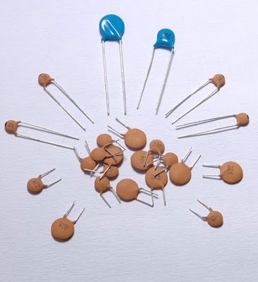
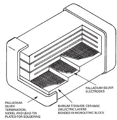
Ceramic capacitors can store energy with small losses current better filter interference and do not swell in harsh operating conditions. And they do not open and do not explode (there are exceptions in some types of polymer), splashing the remaining components of the circuit with electrolyte.
Have much smaller size In comparison with electrolytic, they heat up less. Life time 100,000 hours and more.
No less common, but they are mainly used in precision electronics with the application on the board itself. Tantalum capacitors are subspecies of electrolytic, but with a stretch.
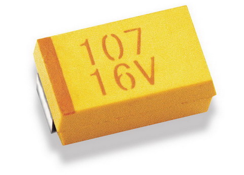
With small sizes, they have outstanding characteristics, as well as long service life. Less sensitive to unfiltered high frequencycomponent, hardy when working with elevated temperaturehave low ESR.